

Piet and Dave
Discussing the compound engine in the Panatela post, I can inform that my spreadsheet is based on a number of polynomials for the steam data. No look-ups.
I shall gladly forward a copy for further investigations. I just brushed it up with English text for "non Vikings".
Dave:
I have not yet looked into your calculations in details, but it seems to be very detailed in finding out just how the receiver pressure varies.
My spreadsheet does not do that. The receiver is expected to be very large i.e. no pressure variations, but it does give the result you explain, namely that the HP power will increase and the LP power will decrease if the LP cut off is increased.
This is due to the fact that the receiver pressure will come down to balance out the increased LP steam consumption, which of cause can not exist.
So - is this really the way to adjust for even power output when everything else is fixed (engine data, steam and condenser data), and how important is it?
Best regards
Jørgen Hansen
Understanding the adjustment of a compound
-
Maltelec

- Master of the Forum

- Posts: 268
- Joined: Sat Nov 14, 2009 7:01 pm
- Boat Name: No Boat Yet
- Location: Cumbria, UK
- Contact:
Re: Understanding the ajustment of a compound
I would imagine the correct way to do it would be to 1st of all, design the engine with ideal but realistic conditions, i.e. a 25 inch vacuum, 60% cutoff or whatever you want to work with etc.
Then you design your engine to suit the calculations.
Once the engine is built, you then fine-tune the engine to give the correct balance of power.
I would say you are correct in that the receiver should be large. After all you can never get the HP and LP to be in sync with each other if nothing else but due to the speed at which the steam moves through the receiver compared to the speed of the engine. You have to make allowances for things which you can't control to prevent them from controlling the engine.
If your engine has been designed to use an air pump, you are at a false start by using it puffing, no matter how much you alter things, you would never get it running right. You need to know how your engine was designed to run, are you using it as it was designed and what do you need to change to make it run as it was designed to.
Engine designers 100 years ago knew what they were doing. It was often the designers of boats who never listened to them, and wanted a state of the art super-slick and shiny boat more than an engineering masterpiece who caused the most problems with poor-running engines.
Not that anything has changed with today's technology.
I've got the vehicle, just need the boat.
-
mcandrew1894
- Full Steam Ahead

- Posts: 193
- Joined: Fri Nov 20, 2009 10:12 am
Re: Understanding the ajustment of a compound
Hi Jorgen,
I'm not Viking, but my wife is!...a bit removed in time though
A fine hardy and beautiful women she is!....Best of all she likes steamboats
Adjusting the HP cut-off will control the amount of power the whole engine makes
Lengthing it will increase the total power, shortening it will decrease the total power.
Adjusting the LP cut-off will control the distribution of power between the HP and LP.
Alright, The double admission you see on my PV diagram is a result of having a HP cut-off that is in excess of 50%. The transfer to the receiver is also noted as part of the calculation.
Additionally, strictly speaking, the diagram only shows one side of the engine, presuming your compound is double acting, the other two PV diagrams need to be accounted for.
A small receiver volume results in large variations on receiver pressure. So how big should the receiver be?
I have found few references with recommendations regarding the size of the receiver volume. Most state that it must be large. which though descriptive, is not very helpful. Herreshoff went to extremes here with enormous receiver pipes.
The two references that I have found on it, recommended:
"The Receiver should be equivalent to the volume of the LP at maximum cut-off"
and
"The Receiver should be equivalent to the swept volume of the LP"
I believe the first one came from Peabody.....The other one may have been Audel.
Regardless, when your engine has a max cut-off in the .88 or .9 range, the difference in volume is small.
I had difficulty in making the receiver this large with a cut off of 75%!
If you have a reference on the size of the receiver, I would like to hear about it.
The receiver also needs to be insulated well, as any heat lost here is lost for good. My receiver could be insulated better....and may yet still.
For small engines, I don't recommend exhaust lap, as the lead should provide plenty of cushion. Piston speeds are low here, and I think piston speed is probably a better measure to determine when an engine should have exhaust lap. Like perhaps over 400-500 feet/minute.
Losses through the cylinder head covers can be significant. Insulating here is something not usually done, but should. I have yet to make the spun brass disks for my engine cylinder heads....its on the list.
Oh yes and another point, the "ideal" compound, ie one that has balanced HP and LP cylinders can only exist at one set of initial conditions.
Stating it another way, if you fix the boiler pressure, and the condenser pressure, and the cylinder ratio, there can only be one solution that will produce equal power to both cylinders.
If your concerned with accuracy, all this matters.....but either way it will push the boat around the lake very nicely.....
Steamboating is a fatal disease....there is no known cure
I'll type more later.
Dave
-
mcandrew1894
- Full Steam Ahead
- Posts: 193
- Joined: Fri Nov 20, 2009 10:12 am
Re: Understanding the ajustment of a compound
Piet's boat appears to be running very well! He is considering changine from a slip eccentric to a Stevenson Link Reverse
I have been thinking....with a compound, it is not always easy to get them to reverse. My engine sometimes doesn't if I stop the engine for 30 seconds or so prior to reversing. I think I get a slug of condensate in the LP and she locks up. Having a piston valve on the LP doesn't help this situation where as a slide valve will lift under these conditions and the slug will clear
I will investigate with my boat this summer. What say the rest of you with compounds? Have any of you changed over from Slip eccentrics to SLR?
Did it help? Was it worth it?
Curious....
oh and I would LOVE a copy of that spreadsheet to look at! I wrote a program for my HP41CV to solve my equations. It worked, but I should really make a spreadsheet of it.
Dave
-
farmerden
- Stirring the Pot

- Posts: 447
- Joined: Fri Nov 20, 2009 12:14 am
- Boat Name: Steam Queen
- Location: Shawnigan Lake B.C. Canada
Re: Understanding the ajustment of a compound
It's interesting that my engine [a compound]starts,reverses,with no assistance from me .It has stevenson link and appears that there is no way for the steam to bypass from the HP to the LP.So the builder obviously knew what he was doing.When I rebuilt the engine and had to retime it I ran the HP on air and adjusted the shaft to the steam chest until the engine sounded smooth then I did the same thing to the LP side.Runs perfect. It would appear the lead and lag are built into the sliding valve and one day when I'm smarter I'll attempt to figure out the math involved.That being said I can fix them',rebuild them,but design them -not yet!!! Den
-
mcandrew1894
- Full Steam Ahead
- Posts: 193
- Joined: Fri Nov 20, 2009 10:12 am
Re: Understanding the ajustment of a compound
Hi Den,
Lead will be a function of the angle of advance and to a certain extent, can be adjusted by moving the eccentric or moving the valve on its nut. The lap is machined into the actual valve components and it is good to center that over the valve travel
Generally, if your events are even, it will run smooth...but we're having fun being academic.
Did you happen to take any measurements of your valve gear while it was off?...and what kind of valve?
Dave
-
farmerden
- Stirring the Pot
- Posts: 447
- Joined: Fri Nov 20, 2009 12:14 am
- Boat Name: Steam Queen
- Location: Shawnigan Lake B.C. Canada
Re: Understanding the ajustment of a compound
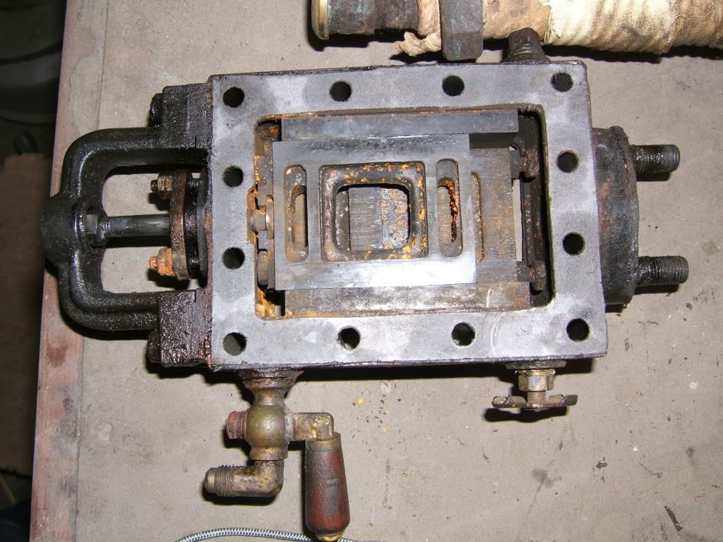
I'll show both the HP and LP Steam valving.This is a balanced pressure type-Correct? My only complaint is not being able to easily spray some WD40 in there during lay-up .Hence the small about of rust.There was no wear and this was the first time theengine had been pulled down since 1987. 
 [/img]
[/img]-
mcandrew1894
- Full Steam Ahead
- Posts: 193
- Joined: Fri Nov 20, 2009 10:12 am
Re: Understanding the ajustment of a compound
It would appear that you have a balanced slide valve. Got any photo's of the steam chest covers? 
Dave
Dave
-
farmerden
- Stirring the Pot
- Posts: 447
- Joined: Fri Nov 20, 2009 12:14 am
- Boat Name: Steam Queen
- Location: Shawnigan Lake B.C. Canada
Re: Understanding the ajustment of a compound
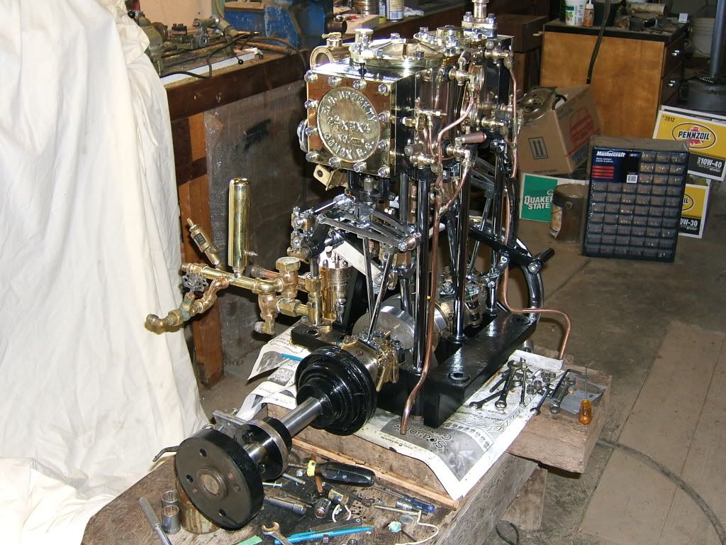
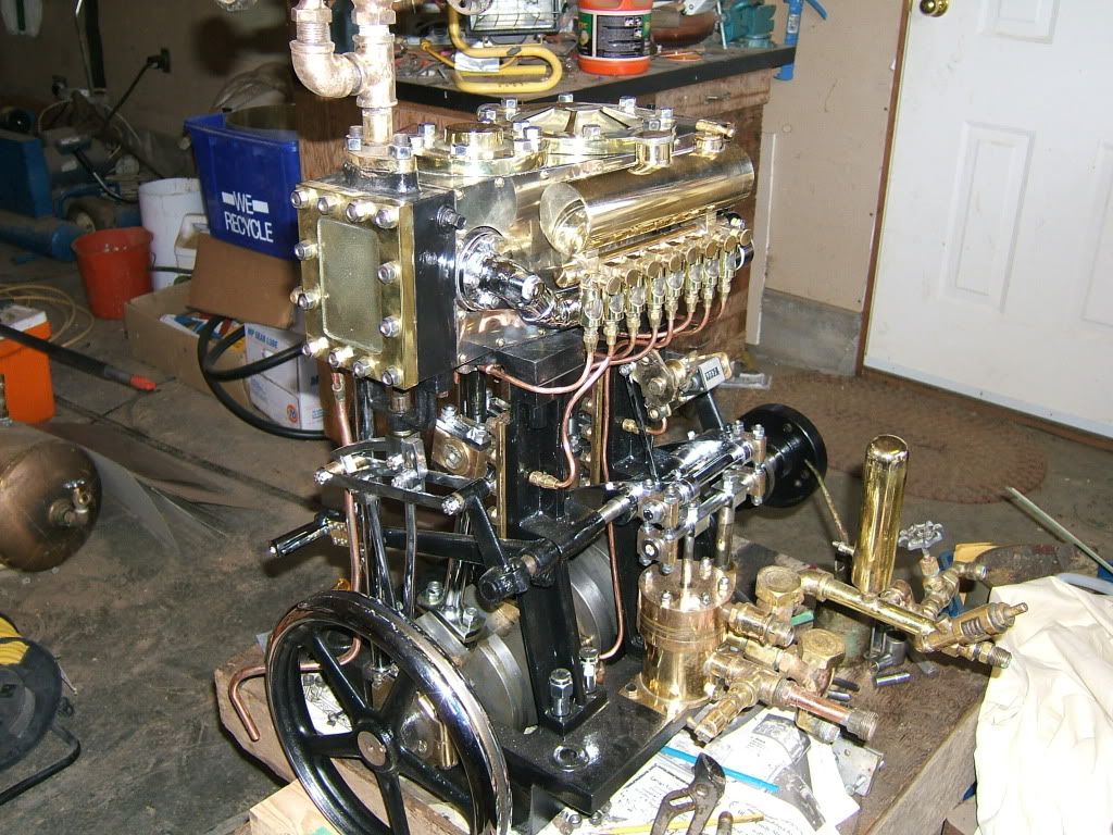
Hi Dave I had to dig deep in the archives! Here is the back side of the steam chest -there is a small spring shown It just keeps enough load against the back side of the valve and the block.The next two shots are of the finished engine showing the steam chest covers.The engine looked good on the bench then I put it back in the boat ,applied liberal amounts of oil and salt water and now it doesn't look as good! However if I just wanted to look at it I would of put a glass plate on top and called it a coffee table! 
 [/img]
[/img]-
farmerden
- Stirring the Pot
- Posts: 447
- Joined: Fri Nov 20, 2009 12:14 am
- Boat Name: Steam Queen
- Location: Shawnigan Lake B.C. Canada
Re: Understanding the ajustment of a compound
You know Dave I was going to put a degree wheel on the engine [similar to timing a camshaft in a car engine] and thinking about it now that would have shown me exactly where cut-off was in relation to TDC -would it not? But I was too eager to get back on the water! Maybe next time I can get more into the science of the whole thing. Den