control of driven hotwell pump
-
shapegenerator
- Just Starting Out

- Posts: 4
- Joined: Thu Oct 08, 2015 12:03 pm
- Boat Name: Not yet named
- Location: Port Angeles, Washington, USA
control of driven hotwell pump
What are some good ways to control the portion of the output of an engine driven pump that feeds water to the boiler from the hot well as needed to maintain desired water level? This engine driven pump normally runs and loops the unneeded water back to the hot well. My boiler and hot well are not located at similar water level heights. I have heard of toilet style float valves being used but am puzzled as to how, as they open when the float is below desired level only in the tank they are located in. Michael
-
Kelly Anderson

- Full Steam Ahead

- Posts: 173
- Joined: Fri Feb 11, 2011 1:28 am
- Boat Name: Vividus
- Location: Strasburg, PA
- Contact:
Re: control of driven hotwell pump
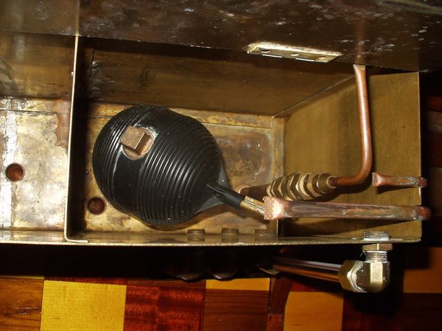
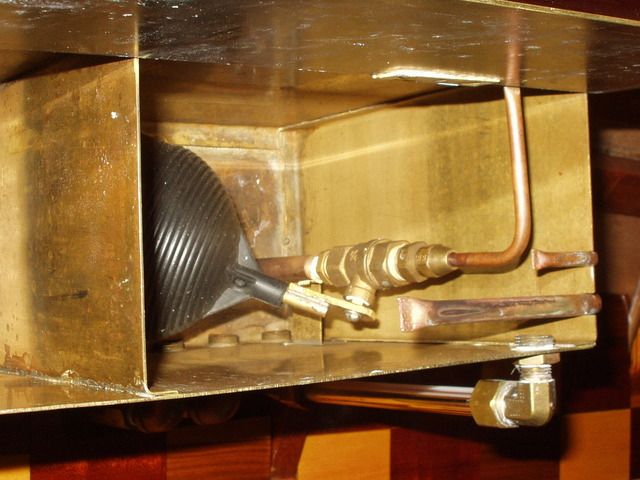
Here are a couple of photos of the float bypass in my last boat. I used a regular toilet float, filled with enough lead sinkers to make it float exactly one half submerged, so it would be heavy enough to drop as well as have enough floatation to rise against the resistance of the float valve.
I used a regular Teflon seat ball valve, with one end backed off from the main valve body enough to reduce resistance to the rotation of the valve to a minimum. The pipe below the valve tees into the feed line from the pump. Also have a manual valve in that line that you can close to override the float bypass valve if needed. The tube above the valve has several holes drilled in its bottom surface to allow the bypassed water to run out in several small streams with a minimum of splashing.
I noted when the valve was just cracked open, and made a lever between the valve stem and the float with the slot for the valve stem indexed to have the valve just begin to open with the float at the half full level. You want the valve to open wider as the level in the hot well drops.
It operates as a primitive logic circuit. With the proper volume of water in the system, if the level in the hot well is low, then the level in the boiler must be high, so more water is bypassed until the hot well is about half full, and vice versa. In operation, the water level in the hot well stabilizes at about half full. If the level in the boiler is below the desired amount, then add some more water to the system from your make up feed tank (or the lake), and you can get the system to stabilize with the desired amount of water in the boiler gauge glass. With the level in the hot well stable, any leaks in the system will cause the water level in the boiler to gradually drop, requiring periodic additions of fresh makeup. The fewer leaking glands, lifting pops, and blowing whistles, the less make up that will be required. I used to need about a gallon of makeup per day of operation.
It was not easy to convince Allnutt. All his shop training had given him a profound prejudice against inexact work, experimental work, hit-or-miss work.
-
Lopez Mike

- Full Steam Ahead
- Posts: 1903
- Joined: Wed Dec 07, 2011 6:41 am
- Boat Name: S.L. Spiffy
- Location: Lopez Island, Washington State, USA
Re: control of driven hotwell pump
I use a very ordinary float that was intended for a live stock water tank. The demands on the float valve are minimal and it's not necessary to use some steam rated unit. The pressures and volumes are in the same range as household water systems.
Another way to explain the system operation is to realize that the total amount of water in the boiler and the hot well is a constant except for whistle, safety valve and leak losses. If you regulate the hot well level, you are regulating (in reverse of course) the boiler level. And all of the regulating mechanism is outside the boiler where you can fiddle with it an repair it and adjust it.
To explain the plumbing in the way I understand it, the output of the feed water pump can go two ways, either into the boiler or to the float and into the hot well. The float is regulating the hot well level just like the tank on your toilet. If you can find one of the older toilet float valves they will work just fine. The new ones are an off and on proposition and would not work nearly as well.
On my power plant there is a constant flow back into the hot well and the level in the boiler sight glass does not move at all during operation. It always surprises me when I see that the level has dropped during the day.
I strongly recommend that you plumb in a hand valve inline with and before the float valve in case the float valve valve sticks open so that you can hand regulate the boiler level.
If you think you are too small to make a difference, try sleeping with a mosquito.
Dalai Lama
Dalai Lama
-
shapegenerator
- Just Starting Out
- Posts: 4
- Joined: Thu Oct 08, 2015 12:03 pm
- Boat Name: Not yet named
- Location: Port Angeles, Washington, USA
Re: control of driven hotwell pump
Thanks for the reply's but I still have a logic problem. I understand completely the need to control the bypass to control the level of the boiler, but have a hiccup in my understanding. In order for any water to enter the boiler it must have a pressure that exceeds the current boiler pressure to open the check valve going into the boiler.
Scenario A: The 200psi engine driven pump always pulls from and feeds the hot well in a loop and the the float valve opens only to divert water to the boiler. The float valve is mounted to be open when the float is level, sending the water to the boiler. It would close when the float drops and the backpressure would open a check valve to the hot well which would need a T fitting on the pressure side of the valve to feed the hot well and bring the water level up in the hot well and then open to the boiler again.
Scenario B: The 200psi engine driven pump always feeds to the boiler and the float valve opens only to divert water to the hot well. The float valve is mounted to be open when the float is dropped and then sends the water to the hot well, and closes when it is again level. The backpressure would open the check valve to the boiler which would still need a T fitting on the pressure side of the valve to feed the hot well through the valve and bring the water level up in the hot well.
Either would seem to work but I am sure one is preferred for safety and function. Is there a way to send part of the driven water back to the hot well and still maintain enough pressure to open the boiler check valve?. You mention small holes but I am unsure of how many or how big and where.
As I am an old airplane guy, complete safety redundancy is always important. The hand pump to add water to both the hot well and in an emergency to the boiler shares no fittings with the driven pump system.
-
Lopez Mike
- Full Steam Ahead
- Posts: 1903
- Joined: Wed Dec 07, 2011 6:41 am
- Boat Name: S.L. Spiffy
- Location: Lopez Island, Washington State, USA
Re: control of driven hotwell pump
Every setup I am aware of uses your scenario B.
In my boat there is a T fitting at the output of the feed water pump. One side goes to the boiler check valve and the other goes through a manual shutoff valve to the float valve. When the float drops slightly, the flow is directed to the hot well. When it rises, the flow goes more to the boiler.
It is not an on/off thing. Most of the time the float valve is partially open. It is one of those quietly effective systems that, once sorted out, just works away in the background. If you have ever run a manual system like a hand valve or injector, you will be pleasantly surprised. And then won't think about it from day to day.
Since my hot well is easily accessed, I don't even have any plumbing to replenish the losses from leaks and whistle use. I have a couple of two gallon plastic jugs full of water and when I notice a long term drop at the boiler sight glass, I dump some water into the hot well. Given my typical boating which runs to lots of small trips with passengers and lots of whistle activity, I find that I need to add a quart or so of water every hour or two.
Since my hot well is much smaller than my boiler, it takes a big glop of water in the hot well to make much difference in the boiler level.
If you think you are too small to make a difference, try sleeping with a mosquito.
Dalai Lama
Dalai Lama
-
shapegenerator
- Just Starting Out
- Posts: 4
- Joined: Thu Oct 08, 2015 12:03 pm
- Boat Name: Not yet named
- Location: Port Angeles, Washington, USA
Re: control of driven hotwell pump
Mike, your comments helped greatly. That most installations used one scenario says much quite simply. Did you have to weight your float or loosen the valve to make it work easily? Did you just keep adjusting the float angle, to engage the valve at the correct portion of flow or do you have a good starting point hint like "always at least twenty percent open going to 75 or eighty percent" ? Thanks, Michael
-
Lopez Mike
- Full Steam Ahead
- Posts: 1903
- Joined: Wed Dec 07, 2011 6:41 am
- Boat Name: S.L. Spiffy
- Location: Lopez Island, Washington State, USA
Re: control of driven hotwell pump
My float valve uses a needle that looks kinda like the one in the float in a carburetor so there is no friction. I can close off the flow by lifting the float with my finger.
Look at the stock tank float valves at a farm supply place.
I set the float so that the water level in the hot tank is as high as it can be and not slop over when the boat rolls around in a wake or waves or people lurching around.
Look at the stock tank float valves at a farm supply place.
I set the float so that the water level in the hot tank is as high as it can be and not slop over when the boat rolls around in a wake or waves or people lurching around.
If you think you are too small to make a difference, try sleeping with a mosquito.
Dalai Lama
Dalai Lama
-
Dhutch

- Full Steam Ahead
- Posts: 168
- Joined: Wed Jan 26, 2011 12:03 am
- Boat Name: SNB Emily Anne
- Location: Staffordshire (UK)
- Contact:
Re: control of driven hotwell pump
We also use the same system, with a float in the hotwell that opens the by-pass when the level drops.
The pump is set to over-pump by around 10-15% or so, such that the by-pass amount is small, but adding a gallon of water into the hotwell will see it arrive in the sight glass in a reasonable time frame.
We also have a pressure relief valve set a little above boiler pressure, such that if the boiler feed valve is closed while the engine is running (or not opened, as more often the case) the pump has somewhere to deliver if the hotwell level closes the float valve.
Daniel
-
Lopez Mike
- Full Steam Ahead
- Posts: 1903
- Joined: Wed Dec 07, 2011 6:41 am
- Boat Name: S.L. Spiffy
- Location: Lopez Island, Washington State, USA
Re: control of driven hotwell pump
I too have a pressure relief valve tee'd off just before the boiler feed water check valve. There are pressure and temperature gauges at this point as well.
The relief valve does not need to be a sophisticated pop valve at all. I have used the relief valve from a domestic hot water heater with the over temp function defeated and the set point adjusted to a bit higher than my boiler pop. As is noted, this relief valve is to protect the plumbing and perhaps anything else like an exhaust feed water heater, superheater, economizer or what ever else might be down stream of the pump and up stream of the float valve.
I use a Hypro feed water pump which produces two pulses per revolution of the pump (and the engine as mine is direct drive) and the feed water pressure gauge shows these fluctuations. Since it is wiggling all the time, I use a glycerin filled gauge to damp things a bit and make the gauge last longer.
I am attuned to normal behavior of this gauge such that any check valve leak back when stopped or poor performance of on one half of the pump due to crud within, is spotted fairly soon (at least when no attractive passengers are aboard).
The temperature gauge is, so far, not useful as my feed water temps are below its lower limit. It is an ordinary automotive coolant dash gauge with a copper capillary tube. When and if I get around to adding some feed water heat this gauge might become useful.
If you think you are too small to make a difference, try sleeping with a mosquito.
Dalai Lama
Dalai Lama
-
fredrosse

- Full Steam Ahead
- Posts: 1906
- Joined: Fri Nov 20, 2009 5:34 am
- Boat Name: Margaret S.
- Location: Phila PA USA
- Contact:
Re: control of driven hotwell pump
"As I am an old airplane guy, complete safety redundancy is always important. The hand pump to add water to both the hot well and in an emergency to the boiler shares no fittings with the driven pump system."
This is a good design philosophy, and perhaps a bit more than required for what is considered redundant steam plant practice. In my experience redundancy is required for "active" machinery, hence two independent means of forcing feedwater into the boiler, but not necessary for all piping and valves. For example, the same suction piping from the feed tank to both pumps will do OK, no need for entirely separate pipes and fittings.
Granted, if the single suction pipe (or its isolation valve) fails, then the function of both pumps is lost, however the probability of this failure is orders of magnitude lower than the failure of an "active" component such as a reciprocating pump.
So in summary, redundant methods for maintaining the boiler safe with respect to maintaining water level, but only for the "active" components. Pipe runs and valves may be non-redundant and still meet criteria.
Pressure indication on the boiler, should have two independent gauges, each with its own gauge isolation valve, so if one gauge fails it can be isolated, with the redundant one available to carry on.
Water level indication on the boiler, should have two independent gauges, each with its own gauge isolation valve, so if one gauge fails it can be isolated, with the redundant one available to carry on. In many cases, a gauge glass with its own isolation valves, plus independent "Try cocks" to allow manual determination of boiler water level if required.
Finally, the boiler safety valve, in the US a single valve is allowed, because "valves" are generally not considered as "active" components. The safety valve however must meet ASME criteria, and be wired such that any tampering with valve settings will be evident to an inspector, and steam tested at least annually. I "test" mine far more often, but only because I forget to kill the fire when docking, so the steam is not being used, pressure climbs, and off goes the safety valve. There must absolutely be no valve or obstruction between the boiler and this safety valve.