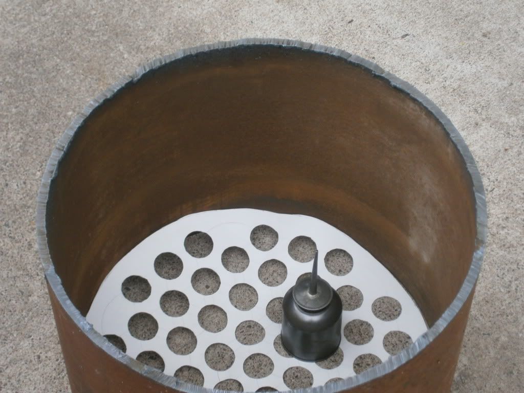
Here's that picture I promised (the Ms. did actually let me borrow her camera...)
Inside the shell is a mock tube plate (meticulously made from card stock with a compass and a box cutter blade) and a neat little plain hand oiler I picked up at a garage sale today for 50 cents. I assume the half a pint of "oil" in it was free.
I think all tube expanders flare the end of the tube a bit. Some boiler tube rollers also bead the tube end, that is OK, but since you are welding the tubes in, an ordinary expander works fine.
The tubesheet holes have to be reamed about 0.004 to 0.008 over tube size for expanded tubes, when I had my tubesheets made the holes were perfect, but I specified 1.250 diameter, and that was too tight for the 1-1/4 inch boiler tubes. I had to open up the holes to 1.255, then everything went together easily.
I guess there are many ways to make the tubesheet, CNC machining, old drill press, punching, laser cut or water jet, etc., but the holes do need to be reamed in the end.
I remember years ago I had a very high bid price for drilling and reaming some tubesheets, and when I asked the shop why such a high price, they said the precision layout of the tube spacing was the reason for the high price. When I told then that the centers spacing could be off by as much as 1/16 inch, and it was OK to just tape the full size drawing to the plate and centerpunch all the holes, the price dropped to less than a third of their original estimate. The machinist thought he was going to be making a precision machinery part, since the spec for reamed holes was a close tolerance. The tubesheet shown on my 23 Feb post in this thread was the one I am talking about. That boiler ran 24/7 for 4 years starting in 1980, and I hydro tested it at 550 PSI a couple of years ago.
The last set of tubesheets I had made were very inexpensive, and the holes spacing was so good that the tubesheets could be clamped together and all the tubes would slide thru, you could then rotate one tubesheet 60 degrees and the tubes would still all slide thru. This was with tube OD and reamed holes with less than 0.001 inch clearance! I could not produce that kind of precision, but the shop that made the parts must have had a real tight CNC setup working to well under +/- 0.0001 inch. Certainly no need for that kind of precision on boiler tubesheets. The attached photo shows these tubesheets, they were so precise I even felt badly welding to them.
The cut of your shell looks good in the photo. If the shell cut is square and a little longer than your final dimension, (you mentioned much grinding to do by hand), then perhaps you can order your tubes a little longer and save the grinding time? I can almost see steam rising inside that shell, I’m sure you can too?
Valves, I buy everything on e-bay, USA brand names like NIBCO, Milwaukee, Stockham, Jenkins, Crane, Apalo, etc. 125 or 150 SWP (Steam Working Pressure) rated. The imports may be OK, but I trust the name brands.
Attachments
tubesheets from machine shop.jpg (58.76 KiB) Viewed 6526 times
Try to make sure the globe valves you buy have a bonnet with a separate threaded locking collar where it goes into the body of the valve, NOT a one-piece bonnet that threads directly into the body of the valve. In locomotive practice the former is the standard as there have been horrific accidents from the latter (bonnet assembly coming out under pressure).
This is a long post about valve accidents and simple brain farts so you may bypass it if you are bored (quite rightly) by stories.
There was a death by scalding on a locomotive in Shelton WA a few years ago caused by unscrewing the big nut rather than the small nut on a bonnet type steam valve while the boiler was under pressure. End of story #1.
My father received fairly serious hot water burns some years ago while we were trouble shooting an injector failure on a 90 ton Shay locomotive. This blunder was done by two very experienced people one of which had worked on full sized locomotives since the 30's, him, and another who stood right there and let him do it, Me. No excuses.
The incident started with a progressive injector loss of performance over a short time. Almost always this had been caused by gunk from the tender getting past the tender screen. This proved to be the case.
In this installation, the output of the injector was fed into the boiler at about half way between full and half water level through a check valve and a shut off valve of the sort shown in Wes's post. Normally all that is needed to work on the injector is to close the shut off valve. When we closed the valve, the valve failed through the stem going on through the moving part. This meant that we would have to shut down the boiler.
So that we could get going the next day, a revenue day, we filled the boiler slowly with cold water with the malfunctioning injector. When the level was to the top of the glass, the steam gauge read zero and holding open the whistle valve gave no flow, we went to the front of the boiler to open up the busted valve. At this point, our minds ceased to function.
The valve was at least three feet below the water level. The water was under no steam pressure but was probably still at near boiling temperature. With a head of three feet (about 1.5 psi) the resulting boiling water fountain was catastrophic. I was on the ground. He was leaning over the valve with a large wrench. The underside of his upper right arm got the full spray through his coverall sleeve raising burn blisters the size of walnut shells.
We did first aid, I repaired the valve, cleaned out the injector, fired off the boiler and brought things up to a normal Saturday night shutdown. Top of the glass and ready to pop. We then drove to a hospital for follow up care. The next day we ran as usual.
Lessons: Stop and think at each step when working with pressure and heat. In this case, we forgot that not all pressure shows on a gauge. I still have the failed valve part on my shelf for reflection.
If you think you are too small to make a difference, try sleeping with a mosquito.
Dalai Lama
I went back and looked at those valves, one piece bonnets. Are Milwaukee valves made in WI? I'm a sucker for stuff made right here by cheese heads.
I'm going to make a tube sheet template out of mdf board and layout the hole spacing exactly how I did with the tag board. I'll then drill out the center holes and use that template to transfer the spacing onto the 3/8" tube sheets.
Again I'll take pictures
Mike I would like to thank you for sharing your first hand experience. It's stories like these that need telling. I welcome anyone else to share similar accounts.
Rolled in tubes is traditional NA practice. The weld - a single pass 6010 - is mere heat transfer from the tube to the tube sheet. It is miss-named a "seal" weld, for it doesn't seal anything. This weld is very important in higher heat apps on the firebox/combustion chamber end to keep the tube ends from melting. Rolling is much stronger than the single pass heat transfer weld. (I have spent days re-rolling in tubes and dressing and grinding and re-welding cracked welds where the tubes weren't rolled in properly the first time. In the Philadelphia School System, Fred ...) If done properly the "seal" weld won't touch the chamfer edge of the tube sheet hole, being between the outside of the tube bead and the sheet face proper.
Nowadays some shops will weld in tubes, and for our size boilers, I guess it's okay. Being the knuckle-head traditionalist that I am, when I build my Scotch which is coming off the drawing boards, I'll roll and bead and transfer weld the combustion chamber ends, and just roll and bead the hood end. I can't wait ...
After expanding the tubes, some use a seal weld on the joint, as shown on previous post.
Just welding the tubes into the tubesheet without expanding them first is not good practice. This is because there would be small gaps between the tube OD and the tubesheet hole, and these gaps would tend to accumulate and concentrate dissolved solids in the water. There would be no way to effectively remove these deposits, and they can cause problems at this critical joint.
When expanding tubes, the tube OD and tubesheet hole should be very clean, with no oil or other coating, just bare clean metal. The tube expander should be dipped into a can of oil and fully submerged to lubricate all of these parts during the expanding process.
fredrosse wrote:MTNMAN, from a post 28 Feb on this thread:
Just welding the tubes into the tubesheet without expanding them first is not good practice. This is because there would be small gaps between the tube OD and the tubesheet hole, and these gaps would tend to accumulate and concentrate dissolved solids in the water. There would be no way to effectively remove these deposits, and they can cause problems at this critical joint.
I would have thought that if you wanted to weld the tubes only, you would want full penetrative welds with absolutely no voids whatsover between tube and tubeplate?
EU/BS practice is that expanding and/or peening is sufficient for most applications, and as fredrosse says the holes must be reamed, to a polish if possible, tubes perfectly round, and again as clean and highly finished as possible.