A special section just for steam engines and boilers, as without these you may as well fit a sail.
-
barts
- Full Steam Ahead

- Posts: 1070
- Joined: Wed Nov 18, 2009 6:08 am
- Boat Name: Otter, Rainbow
- Location: Lopez Island, WA and sometimes Menlo Park, CA
-
Contact:
Post
by barts » Tue Jul 06, 2021 10:21 pm
Steam Captain wrote: ↑Mon Jun 14, 2021 2:24 pm
Correct, a syphon won't work. The elasticity brought into the equation by adding a syphon would completely ruin any recognizability of a pV-graph.
I've tried to get my hands on a pressure transducer, but the answer I got was always "We only sell to commercial buyers" - Those pressure sensors would have been perfect. They worked up to 400°C and covered all pressure ranges below the Gpa scale. And they were small (M5 thread). BUT they didn't want to sell.
I secretly settled for spark plug pressure sensors right now unless there'll be a source of a good pressure sensor to switch them out. The challenge is, that almost all pressure sensors on the buyable market are not suitable because they simply measure too slowly and not just a little, but several orders of magnitude too slowly.
A siphon filled w/ water should have very little effect on the response of the pressure transducer.
I've had very little difficulty buying components of all sorts, esp. over the web.
https://www.amazon.com/Thread-Stainless ... r=8-2&th=1
The above claims a response time of less than 1 mS; this should be sufficient to characterize performance at 300 rpm (5 rev/sec ) or so; it'll be a bit squirrely around valve opening events.
-
DetroiTug
- Full Steam Ahead
- Posts: 1863
- Joined: Fri Nov 27, 2009 5:56 pm
- Boat Name: Iron Chief
- Location: Northwest Detroit
Post
by DetroiTug » Wed Jul 07, 2021 12:08 am
''A siphon filled w/ water should have very little effect on the response of the pressure transducer''
I thought that too first reading that a while back and there's likely a sleight of hand involved, but how could it be kept completely full?
An idea I had but never posted, was a bleeder at the top of the loop, mount the siphon upside down and plug it's entry with a hard neoprene ball. As long as there as there is very little air in the siphon the ball would barely move. That would do well to eliminate any compression, hold the water and isolate the temperature.
Plugging it with a rubber ball, a siphon would likely not even be needed, a straight pipe would suffice.
-Ron
-
cyberbadger
- Full Steam Ahead
- Posts: 1123
- Joined: Thu Nov 07, 2013 9:16 pm
- Boat Name: SL Nyitra
- Location: Northeast Ohio, USA
Post
by cyberbadger » Wed Jul 14, 2021 3:04 am
barts wrote: ↑Tue Jul 06, 2021 10:21 pm
I've had very little difficulty buying components of all sorts, esp. over the web.
https://www.amazon.com/Thread-Stainless ... r=8-2&th=1
The above claims a response time of less than 1 mS; this should be sufficient to characterize performance at 300 rpm (5 rev/sec ) or so; it'll be a bit squirrely around valve opening events.
Pretty decent for so cheap. I got the 0-300psi version.
I am using an arduino with a data logger shield(SD card slot and a button cell backed up Real time clock for timestamps). The arduino only has 10bit Analog to Digital convertors, but it already seems sufficient to test further under steam.
This is the arduino data capture with the pressure sensor hooked up to an air compressor.

- pressuresensor.jpg (87.8 KiB) Viewed 7685 times
-CB
-
barts
- Full Steam Ahead
- Posts: 1070
- Joined: Wed Nov 18, 2009 6:08 am
- Boat Name: Otter, Rainbow
- Location: Lopez Island, WA and sometimes Menlo Park, CA
-
Contact:
Post
by barts » Wed Jul 14, 2021 4:28 pm
Very nice results. I'm not sure how fast your Arduino can sample, but I'd make sure to low-pass filter your pressure signal, w/ a cut-off frequency of half your sampling rate (
https://en.wikipedia.org/wiki/Nyquist_frequency). Even a simple RC circuit will help reduce aliasing. W/ an inexpensive encoder driving sampling on each count, your indicator should work pretty well.
- Bart
-
cyberbadger
- Full Steam Ahead
- Posts: 1123
- Joined: Thu Nov 07, 2013 9:16 pm
- Boat Name: SL Nyitra
- Location: Northeast Ohio, USA
Post
by cyberbadger » Wed Jul 14, 2021 8:57 pm
barts wrote: ↑Wed Jul 14, 2021 4:28 pm
Very nice results. I'm not sure how fast your Arduino can sample, but I'd make sure to low-pass filter your pressure signal, w/ a cut-off frequency of half your sampling rate (
https://en.wikipedia.org/wiki/Nyquist_frequency). Even a simple RC circuit will help reduce aliasing. W/ an inexpensive encoder driving sampling on each count, your indicator should work pretty well.
- Bart
The points in that graph are averages of 10 acquisitions.
I'm not really sure yet the exact aquisition rate, and I'm sure it will change. Each analogRead() function takes only 0.0001 s to complete. Right now I'm printing some very long well formated string csv records, that's pretty cpu intensive. If I just printed the timestamp and raw values I'm sure I could get a faster rate.
It may be a full indicator eventually, but for this summer I'm going to get another pressure sensor on the other cylinder, so 2 total. I'm going to try and get a baseline of hopefully like 5 hrs of steaming.
-CB
-
barts
- Full Steam Ahead
- Posts: 1070
- Joined: Wed Nov 18, 2009 6:08 am
- Boat Name: Otter, Rainbow
- Location: Lopez Island, WA and sometimes Menlo Park, CA
-
Contact:
Post
by barts » Wed Jul 14, 2021 9:37 pm
If you can acquire the piston position via an encoder pulse and trigger sampling with that, you may find it easier to analyze the data w/o needing to infer position via valve events - particularly if you change cut-off during the sampling period. Some incremental encoders have a Z or index pulse; this can be used to compare results for a complete revolution easily. In fact, this would let you compute the area under the curve and provide a real time display of indicated HP (assuming appropriate constants were entered). If need be, you could sample every other revolution and do computes in the other.
- Bart
-
cyberbadger
- Full Steam Ahead
- Posts: 1123
- Joined: Thu Nov 07, 2013 9:16 pm
- Boat Name: SL Nyitra
- Location: Northeast Ohio, USA
Post
by cyberbadger » Mon Jul 19, 2021 10:32 pm
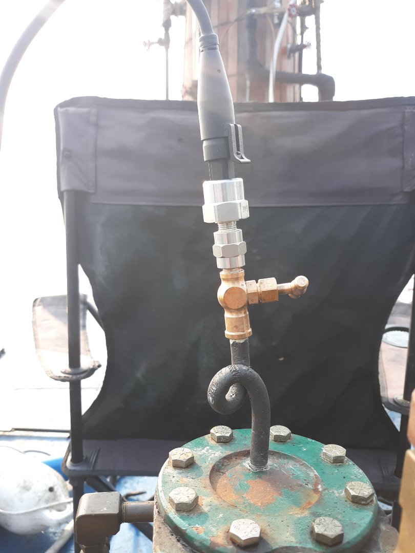
Well I heat bended a 6" threaded sch80 seamless steel 1/8" pipe into a siphon.
Glorious data and the arduino data recorder can store many hrs on the microsd card.
Seems this sensor is ok with the steam pressure and heat in this configuration.
Unfortunately this datalogger still can't clean the soot on the firetubes....
-CB
- 20210719_182327.jpg (97.77 KiB) Viewed 7590 times
Last edited by
cyberbadger on Mon Jul 19, 2021 10:33 pm, edited 1 time in total.
-
cyberbadger
- Full Steam Ahead
- Posts: 1123
- Joined: Thu Nov 07, 2013 9:16 pm
- Boat Name: SL Nyitra
- Location: Northeast Ohio, USA
Post
by cyberbadger » Mon Jul 19, 2021 10:32 pm

- Screenshot_20210719-174805_Sheets.jpg (62.75 KiB) Viewed 7589 times
This is over 20-25minutes. The scale is psi.
This is impressive to me in that it works and it is the first steam pressure data I have gotten.
Just don't consider it the max performance I can or have gotten, it's just preliminary data taking it easy with the engine.
-CB
-
cyberbadger
- Full Steam Ahead
- Posts: 1123
- Joined: Thu Nov 07, 2013 9:16 pm
- Boat Name: SL Nyitra
- Location: Northeast Ohio, USA
Post
by cyberbadger » Tue Jul 20, 2021 1:57 pm

- 20210720_095416.jpg (24.42 KiB) Viewed 7553 times
Interesting, the sensor shows after the engine is shut off a vacuum of 10psi develops and then dissipates.
-CB
-
barts
- Full Steam Ahead
- Posts: 1070
- Joined: Wed Nov 18, 2009 6:08 am
- Boat Name: Otter, Rainbow
- Location: Lopez Island, WA and sometimes Menlo Park, CA
-
Contact:
Post
by barts » Tue Jul 20, 2021 2:26 pm
cyberbadger wrote: ↑Tue Jul 20, 2021 1:57 pm
Interesting, the sensor shows after the engine is shut off a vacuum of 10psi develops and then dissipates.
Given that you're watching the cylinder cool down and the steam inside condense, this makes perfect sense.
- Bart


