Page 7 of 14
Re: digital steam engine indicator
Posted: Fri Mar 29, 2019 9:43 pm
by Mike Rometer
Basicaly, the ones I've seen are a ring round the crank with 36 notches the one at TDC is larger as calibrator. The notches are read by a small coil with a magnetic core. Don't ask about the attatched electronics, that's beyond my ken, but I believe they can calculate the crank position to better than 0.1 of a degree, and with other sensors on the engine set the ignition to the optimum for the prevailing conditions, speed, load, etc.
The reluctor ring is usually fitted to the flywheel, or occasionally the front pulley.
Understand that I have been retired for more than 20 years and for the last 5 of working was no longer involved with such things, so methods will undoubtedly have changed/improved, but a little research should turn something usable up.
Re: digital steam engine indicator
Posted: Sat Mar 30, 2019 2:04 am
by Lopez Mike
There is just such a thing on the front of many car engines. A ring with all of the notches and a sensor that tells the car's black box when to send juice to each spark plug and when to activate the fuel injectors. You local wrecking yard can be your friend.
Re: digital steam engine indicator
Posted: Mon Apr 01, 2019 2:02 am
by marinesteam
Mike Rometer wrote: ↑Fri Mar 29, 2019 9:43 pm
Basicaly, the ones I've seen are a ring round the crank with 36 notches the one at TDC is larger as calibrator. The notches are read by a small coil with a magnetic core. Don't ask about the attatched electronics, that's beyond my ken, but I believe they can calculate the crank position to better than 0.1 of a degree, and with other sensors on the engine set the ignition to the optimum for the prevailing conditions, speed, load, etc.
The reluctor ring is usually fitted to the flywheel, or occasionally the front pulley.
Understand that I have been retired for more than 20 years and for the last 5 of working was no longer involved with such things, so methods will undoubtedly have changed/improved, but a little research should turn something usable up.
Prior to modern fast electronics, less resolution was wanted due to the time needed to acquire & process the input. At a constant speed it is possible to calculate a position accurately but you can never have a known position better than 10 degrees with the example given. When sensor and processor speeds weren't what they are now an analog device called a resolver was often used to determine position as digital devices (encoders ) were too slow. Now, modern encoders can be used at quite high speeds without issue with sub degree accuracy at very low cost. No need to reinvent the wheel as you can get an appropriate encoder for arduino for about $40 usd, like this one:
https://www.kr4.us/rotary-encoder-200-p ... gJHBvD_BwE.
Cheers
Ken
Re: digital steam engine indicator
Posted: Wed May 08, 2019 3:16 pm
by Steam Captain
Exactly. I think an encoder would do the trick. I am still not sure how an reluctor works, but if it is the ignition timer thing I had in my car, I suspect it would be usable for rpm messuring, but not for a good diagram - at least as far as I understand magnetic reluctors. But rotary encoders seem to be a good choice, as they are cheap and can messure even more points per rotation than needed after all.
I guess I confuse a reluctor with a distributor - never mind.
Re: digital steam engine indicator
Posted: Mon Feb 17, 2020 10:22 pm
by Steam Captain
So,
Unfortunately, I've not found time for my interests, but I've now proceeded with the digital steam engine indicator.
I've now fully finished everything going on on the x-axis of the indicator diagram. Fortunately, this has been the more complicated part. To accomplish this, I've sherlocked the internet for similar Arduino projects and tried different source codes, cut something out, added something else, read something, until I could create something useful.
These are the schematics of the system I figured:
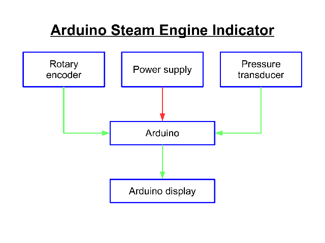
There were several considerations, that brought my attention to the Arduino. It is a very low requirement micro controller with open source and a large fan base with an abundant supply of tutorials, manuals and lots of source code, called "sketches", shared openly without any limitations. Furthermore, the Arduino can take a large variation of voltage as the power supply, while needing only very little currency, making it perfect for energy sources, where a highly accurate voltage regulation isn't needed.
The physical assembly is as simple as it can get. I took an incremental encoder, which has 5 cables. Ground goes to the Arduino board ground, one cable goes to the 5V Arduino on-board pin and the other 2 cables go to 2 of the input pins. Unfortunately, pressure transducers often get the same name as pressure switches in german. So, I bought the wrong thing. But actually, adding the pressure transducer will be the most simple step.
What I thought the biggest challenge was, turned out to be not all too challenging. I think going into the detail of the code would be too much here. In general, I just calculated degrees from the encoder signal, converted degrees to radians, use the standard piston position equation and shifting it on the x- and y-axis in preparation for the graphing of the pV-diagram. That's the step I am doing right now.
After that, I want to test it and format the Arduino code and create something like a manual for everyone to use.
Re: digital steam engine indicator
Posted: Tue Feb 18, 2020 3:13 am
by TahoeSteam
That's wonderful Ramón. I'd be willing to buy a set and coded package if you were to market it. (I have no coding experience, nor desire to use my limited availability of cranium space to learn it...)
Re: digital steam engine indicator
Posted: Tue Feb 18, 2020 4:08 am
by fredrosse
Me too. Electronics are not any strong point for me, but I do have four electronic pressure transducers, rated to 100 psi, with a claimed response time of 0.001 seconds. Would love to be able to make Pressure-Stroke diagrams for my engines.
Re: digital steam engine indicator
Posted: Tue Feb 18, 2020 7:37 pm
by Steam Captain
Well, I'll not be making money off of this. This is a project, which is interesting for me and if it can be helpful for others, it is reward enough.
I actually have cheap pressure transducers in mind, which are available for different pressure arrays and have a reaction time of 1-2 ms. I suspect these are the ones you also have. OK, back to coding now:)
Re: digital steam engine indicator
Posted: Tue Feb 18, 2020 8:14 pm
by DetroiTug
Big fire = go fast.

All kidding aside, this is an interesting project and I too would be interested in the code.
-Ron
Re: digital steam engine indicator
Posted: Wed Feb 19, 2020 12:55 am
by Steam Captain
I fired a lot tonight:)
To water the mouths, I give a short update of what I've accomplished so far:
- Translation of the encoder signal into the crank angle.
- Calculation of the piston position (The crank radius and con rod length still are written into the code as constants).
- Shifting the piston position function to set the starting point on the x-value zero. In short: TDC is 0. This will be important for the pV-diagram and further calculations.
- The calculation of an average pressure and the automatic identification of the maximum and minimum pressure. This way, the pressure doesn't even need to be put into the system. The Arduino handles it on itself.
Things I still need to do:
- The separate integration of the area under the pressure curve from 0° to 180° and from 180° to 360° - almost done.
- Inserting a subroutine to calculate the RPM - almost done.
- The calculation of the indicated power.
- Getting rid of the pc - using a display for output and a small keypad for the input of the individual variables like con rod length, stroke, piston diameter. This way, noone really needs to get into the code and thus is much less "techie". My aim is to create a system, that is very easy to use. I will also avoid the touchscreen function. Every input only works over the sensors and keypad. Hands can get dirty when handling an engine. So, a touchscreen function wouldn't be smart.
- Either asking the user if the imperial or metric system should be used or providing two codes. But I slightly prefer the former way.
The biggest challenge I see right now is to test the system on a real engine. It can be, that the code I am using right now has to be adapted to fast rpms to avoid false signals. The only thing I'm not satisfied with is the need to turn the engine on TDC manually before the Arduino is started. Even though it'll make it a little more complex, I was thinking of something like a simple Hall or Reed sensor and a disk, which sends a ping whenever the engine reaches TDC. This way, even IF there are false readings shifting the pV-diagram out of phase, the system would self-rectify it with a type of TDC pinger. Actually, it's like creating an absolute encoder from an incremental one.
One thing I am just realizing right now is, that I've not been thinking about the 2 sides of the cylinder, as I always had my engine in my mind. It would actually be very interesting to have the option of getting the pV-diagrams of both sides. In other words, I think I buy 2 pressure transducers
