Opposed-Piston Engine Project - The Steam Version
Posted: Tue Jan 15, 2019 9:10 am
Ahoi,
I want to talk about a steam engne concept, that is, I assume, very out-of-the-box. The development of the steam engines during the time, when turbines and IC engines were about to take over as the prime marine propulsion methods, always caught my interest. Especially the uniflow principle, that created a design heavily resembling 2-stroke engines. From that time, I found some very interesting designs of steam engines adapting a design now usually associated with car engines. Single action pistons with cross-head-less crankshafts running in an oil sump and cam-shaft-actuated poppet valves mae it possible to have fast-running steam engines.
There are a lot of youtube videos of IC engines being converted into steam engines by crafty folks and the idea to use existing and cheaply available IC engine parts really caught my interest. At the end, I was thinking and designing around a lot with poppet valves and I found an issue, that hasn't been adressed by the steam engine conversions on youtube (although there is an amazing site called "Kimmelsteam", that has a lot of car and boat engines, that were converted to steam in an amazingly professional way, with lots of ways to address the steam distribution. It is a very interesting site.
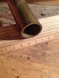
So, after the compressor I wanted to convert turned out to be broken, I accidentally found very cheap crankshafts on ebay for chainsaws "made in China". They cost like around 10€/$. I can not even explain how perfect these crankshafts are for my experimentings. Since they are cheap, it is not a big loss if the project hits rock bottom. So, now I have access to cheap crankshafts and I came back to the sublect of pondering about the valve timing. My plan is to have a fast-running IC-like steam engine. This is the reason why I wanted to stick with piston valves. But then I've come across this:
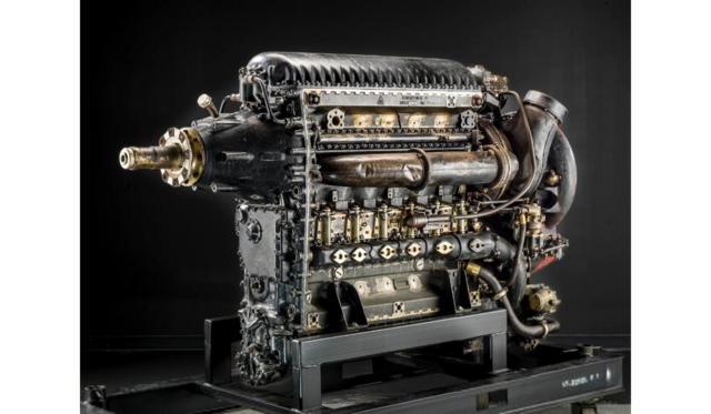
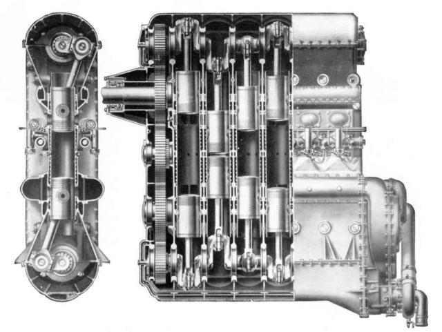
This is actually an airplane engine from Junkers, called Jumo 205 if I remember correctly. This is a very interesting design. It works under the 2-stroke principle with inlet and exhaust ports in the cylinder liner. The thing is, you can find lots of 2-stroke steam engine conversions, that make use of the unchanged ports in the engine. But they are designed for 2-stroke IC engines. So, the people end up with lots of steam pressure wasted through the ports (Yet it is still awesome people build them and they do work after all). This issue can be resolved by changing the location of the ports in a custom-made liner. So far so good. But I was wondering of how it would be able to control the steam engine's power output without throttling the steam. The location of the ports can not be modified (except some sliding liner models like the Knight engine) but here comes the trick: The opposed piston engine uses 2 pistons in one liner. When I saw a gif of an opposed piston engine, that showed, that the 2 pistons don't move entirely synchronized, but one piston moves some degrees ahead of the other to provide for a better efficiency in cylinder filling and exhausting. On to my project:
The points above mean, that in an opposed piston design for a steam engine, each piston actuates/times either the inlet or the exhaust ports in the liner with no need to use any
other valves whatsoever. I foresee one challenge though: The crankshafts need to be coupled by gears of some type and the only way to alter the power output of an engine would be to change the rotational angular alignment of the crankshafts to each other by means of this gear. Technically it is very simple to do, for example via a chain gear. But the point is, that despite the relatively small amount of power used to work the "normal" steam valve gears, this design has to handle the full power of the engine going through the gear. So, the mechanism needs to be very sturdy. I was thinking of a governor, but I don't know it the governor used in this special occasion would swallow too much energy, since it works against all the engine's power. Please let me know if you know of any governor design, that can do the trick. But for a boat engine, that can run under very constant conditions (in comparison to a car engine) I think a manual mechanism could work fine.
This is a very out-of-the-box project and it will be very exiting to realize. Now, I have to buy the raw materials for the engine and the boiler:)
I want to talk about a steam engne concept, that is, I assume, very out-of-the-box. The development of the steam engines during the time, when turbines and IC engines were about to take over as the prime marine propulsion methods, always caught my interest. Especially the uniflow principle, that created a design heavily resembling 2-stroke engines. From that time, I found some very interesting designs of steam engines adapting a design now usually associated with car engines. Single action pistons with cross-head-less crankshafts running in an oil sump and cam-shaft-actuated poppet valves mae it possible to have fast-running steam engines.
There are a lot of youtube videos of IC engines being converted into steam engines by crafty folks and the idea to use existing and cheaply available IC engine parts really caught my interest. At the end, I was thinking and designing around a lot with poppet valves and I found an issue, that hasn't been adressed by the steam engine conversions on youtube (although there is an amazing site called "Kimmelsteam", that has a lot of car and boat engines, that were converted to steam in an amazingly professional way, with lots of ways to address the steam distribution. It is a very interesting site.
So, after the compressor I wanted to convert turned out to be broken, I accidentally found very cheap crankshafts on ebay for chainsaws "made in China". They cost like around 10€/$. I can not even explain how perfect these crankshafts are for my experimentings. Since they are cheap, it is not a big loss if the project hits rock bottom. So, now I have access to cheap crankshafts and I came back to the sublect of pondering about the valve timing. My plan is to have a fast-running IC-like steam engine. This is the reason why I wanted to stick with piston valves. But then I've come across this:
This is actually an airplane engine from Junkers, called Jumo 205 if I remember correctly. This is a very interesting design. It works under the 2-stroke principle with inlet and exhaust ports in the cylinder liner. The thing is, you can find lots of 2-stroke steam engine conversions, that make use of the unchanged ports in the engine. But they are designed for 2-stroke IC engines. So, the people end up with lots of steam pressure wasted through the ports (Yet it is still awesome people build them and they do work after all). This issue can be resolved by changing the location of the ports in a custom-made liner. So far so good. But I was wondering of how it would be able to control the steam engine's power output without throttling the steam. The location of the ports can not be modified (except some sliding liner models like the Knight engine) but here comes the trick: The opposed piston engine uses 2 pistons in one liner. When I saw a gif of an opposed piston engine, that showed, that the 2 pistons don't move entirely synchronized, but one piston moves some degrees ahead of the other to provide for a better efficiency in cylinder filling and exhausting. On to my project:
The points above mean, that in an opposed piston design for a steam engine, each piston actuates/times either the inlet or the exhaust ports in the liner with no need to use any
other valves whatsoever. I foresee one challenge though: The crankshafts need to be coupled by gears of some type and the only way to alter the power output of an engine would be to change the rotational angular alignment of the crankshafts to each other by means of this gear. Technically it is very simple to do, for example via a chain gear. But the point is, that despite the relatively small amount of power used to work the "normal" steam valve gears, this design has to handle the full power of the engine going through the gear. So, the mechanism needs to be very sturdy. I was thinking of a governor, but I don't know it the governor used in this special occasion would swallow too much energy, since it works against all the engine's power. Please let me know if you know of any governor design, that can do the trick. But for a boat engine, that can run under very constant conditions (in comparison to a car engine) I think a manual mechanism could work fine.
This is a very out-of-the-box project and it will be very exiting to realize. Now, I have to buy the raw materials for the engine and the boiler:)