It does seem possible to have the
kind of boiler I described in my thread here:
viewtopic.php?f=8&t=2111
but I decided for a non-solid fuel burner. After studying lot's of material, the boiler should be/do/have:
- The ability to feed my opposed-piston steam engine for R&D. (The following thread accompanies the engine project: viewtopic.php?f=8&t=2120&p=18241#p18241)
- A watertube boiler.
- An easily quantifiable means to regulate the burner. Thus, solid fuel is excluded (not talking about dust firing as it seems to be an undiscovered country for the small scale)
- A focus on radiation HS.
- A convection HS tube bundle.
- An economizer.
- A superheater before or even behind the convection HS.
- An air preheater
- A steam separator.
- A single, but redundant feed water pump.
Here is the link. It is in german, though. But the pictures possess all the crucial information of the text:
https://www.messerforum.net/showthread. ... l%F6tlampe
The step from a blowlamp forge to a blowlamp boiler was naturally just a small step for me.
The boiler will be defined by the N-shaped travel path of the combustion gasses. The left bar of the N will be the burning chamber with the water wall acting as a radiation HS. 4 burners will create jet-flames looking upwards. The idea behind it is to elongate the flame with this means. Each 2nd tube on the top side will be cranked out to allow for the passage of the combustion gasses.
A sheet metal bow will lead the gasses to the middle bar of the N, where the superheater, the convection evap and the eco bundles will be in.
The last bar of the N will house the air preheater.
I am building a water-walled burning chamber from copper tubes. I thought of using unmodified blowlamps just placed in a sort of rack besides the boiler and let the burner nozzle stick inside the boiler. But I want to have a vertical flame and blowtorches don't always work with the burner nozzle looking right up or down due to the liquid part of the gasoline getting too close to the burner and cooling it too much.
I'll use brake pipes and nozzles from spraying guns or similiar tools for the burner.(I read someone on this forum used a paintbrush pistol as a burner) - Maybe it is even worth a separate thread.
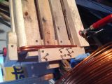
Today, I have thrown together a crude, wooden negative to wrap the copper tube around. This will be the water wall enclosing the burning chamber.
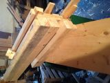
The corners are smoothened with a drawknife to attain a bending radius of 22mm for the 6mm(1/4") copper pipe. This is more or less the minimum bending radius without any fill-ins. The round wooden blocks on top are the place holders for the burner nozzles and will be clamped or screwn on to crank the tubes around for the burner nozzles.
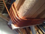
The picture above shows a successful test bend.
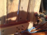
As you can see at the test coiling, the burning chamber will be elongated to have enough space for the jet flames to develop. One short side already shows a cranked tube for the burner. The tubes of the opposite side will be alternating in hight to create space between each of them for the gasses to leave the burning chamber. I'll show in another post what I mean.
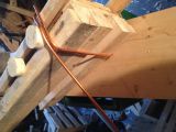
The picture above shows the first complete turn. Hidden is the completed bending of the feed end.
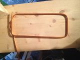
The photo above shows a wooden block I use to hold the coil in place. Using 2 of these blocks and 2 clamps works just right. While the last, finished segment before a bent to make is clamped down like this, the bent is carefully made by hand or a small piece of soft wood with a groove in it. To conclude a bend, the following length of tube is clamped with the second clamp and the first one can be removed to be used after the following bending. This way, I will continue until I reach the end.