OK, the four bridges on the piston valve, plus no piston rings on the piston valve protects from this problem.
On my small steam scanoe engine (75cc, single acting) I originally used piston valve with no rings, but leakage became a problem. I then made piston valve with rings, and leakage reduced very much. But that was a very small engine, 50mm main power piston, 20mm piston valve diameter.
First core box
-
fredrosse

- Full Steam Ahead

- Posts: 1930
- Joined: Fri Nov 20, 2009 5:34 am
- Boat Name: Margaret S.
- Location: Phila PA USA
- Contact:
Re: First core bockes
- Attachments
-
- T47 PistonValveS.jpg (36.63 KiB) Viewed 11734 times
-
- V2-sleeve-bodyS.jpg (17.43 KiB) Viewed 11734 times
-
Rainer

- Full Steam Ahead
- Posts: 306
- Joined: Sun Nov 22, 2009 5:42 pm
- Boat Name: Emma and Molly
- Location: Hannover, Germany
- Contact:
sleeve
I agree with you - also for me a sleeve plus one or two piston rings is the best solution from todays engineering view. For my Arkona engine I even hardened and grinded the sleeve to avoid any wear and tear.
But on other hand this are more parts to build and to align and fit together - and more parts that can become defect.
If you have a fast running piston with low pressure (from todays point of view) you don't have to deal with static pressure in the piston/cylinder gab. You also don't have the need to separate the exhaust from the crank oil like in ic engines. All loss in the HP valve will power the LP (OK, with some loss) but with little groves in the piston valve surface you also can stop some steam travel through it. The steam expands in this gaps and act as a barrier for the following steam. This is a common solution for low leaking not tuching sealings in industry.
Piston valve used on Emma's HP cylinder - picture from June 2005:
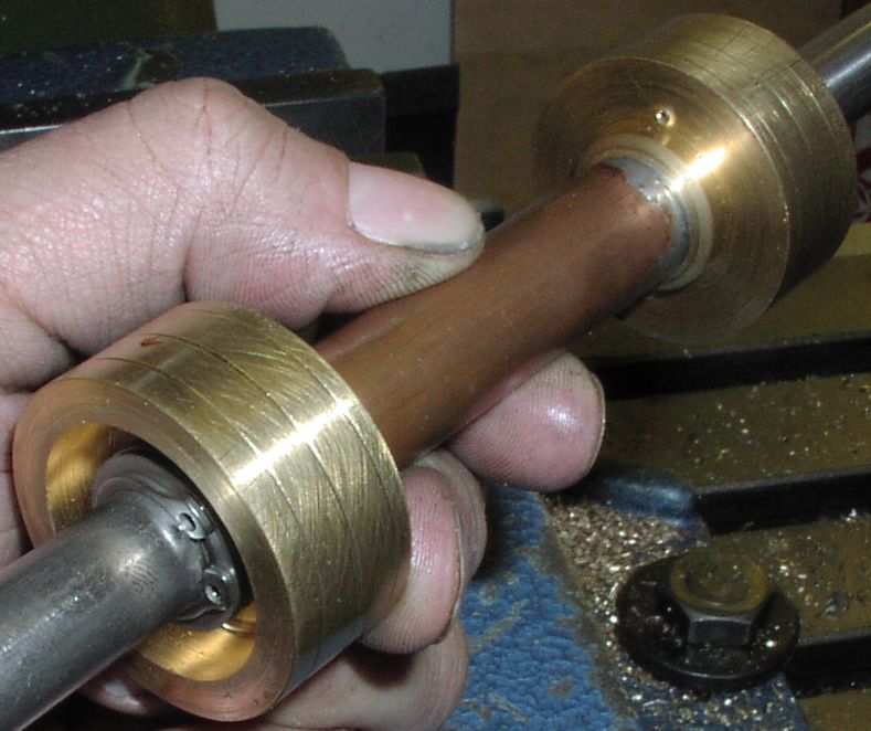
I don't know if the German Navy wanted to keep their engines as simple as possible or if maybe this piston valve type is the first step after the slide valve. Here you also have a big slot direct machined into the casted part as port and two guidances at the D-valve - the outer edges. This present design here is more or less a bended D-valve. Anyway - I will give this KISS design a chance and try out what will happen.
PS
Thanks for the communication about my engine - I always love to communicate with others about "steam". Thats' also the reason why I have neglected my private home page a bit - you do not get any feedback...
But on other hand this are more parts to build and to align and fit together - and more parts that can become defect.
If you have a fast running piston with low pressure (from todays point of view) you don't have to deal with static pressure in the piston/cylinder gab. You also don't have the need to separate the exhaust from the crank oil like in ic engines. All loss in the HP valve will power the LP (OK, with some loss) but with little groves in the piston valve surface you also can stop some steam travel through it. The steam expands in this gaps and act as a barrier for the following steam. This is a common solution for low leaking not tuching sealings in industry.
Piston valve used on Emma's HP cylinder - picture from June 2005:
I don't know if the German Navy wanted to keep their engines as simple as possible or if maybe this piston valve type is the first step after the slide valve. Here you also have a big slot direct machined into the casted part as port and two guidances at the D-valve - the outer edges. This present design here is more or less a bended D-valve. Anyway - I will give this KISS design a chance and try out what will happen.
PS
Thanks for the communication about my engine - I always love to communicate with others about "steam". Thats' also the reason why I have neglected my private home page a bit - you do not get any feedback...
Last edited by Rainer on Wed Dec 05, 2012 12:46 pm, edited 1 time in total.
Rainer
www.steamboating.de
www.steamboating.de
-
Mike Rometer
- Full Steam Ahead
- Posts: 936
- Joined: Sat Aug 13, 2011 6:41 pm
- Boat Name: B.N.Y.S.
- Location: Middle Earth
Re: First core bockes
These small grooves are often termed Labirynth Grooves, and as Rainer says are used all over industry for simple sealing. They will work with any fluid not just steam, and can be amazingly effective. I would suggest a good choice in that situation.
S.U. carburettors (and others) used them both on the air-side and the fuel-side. If they can keep petrol in, they certainly work OK.
S.U. carburettors (and others) used them both on the air-side and the fuel-side. If they can keep petrol in, they certainly work OK.
Retirement is about doing what floats your boat!
A BODGE : - A Bit Of Damn Good Engineering.
A BODGE : - A Bit Of Damn Good Engineering.
-
gondolier88

- Full Steam Ahead
- Posts: 290
- Joined: Fri Jun 18, 2010 8:54 pm
- Boat Name: No Boat Yet
Re: First core bockes
It would be unwise to down-grade the importance of the small guide-bush threaded into both of the PV cylinder covers. Using the taper on the valve rod to completely secure the piston, and making sure that none of the control diameters on the piston valve are shorter than the lengths of the ports- ie. self-bridging. Between all three design features there should be next to zero side-play possible. Of course, threading the bushes could put possible errors into the equation, and push fit bushes with locating shoulders would be the way to go nowadays.
Greg
Greg
-
Rainer
- Full Steam Ahead
- Posts: 306
- Joined: Sun Nov 22, 2009 5:42 pm
- Boat Name: Emma and Molly
- Location: Hannover, Germany
- Contact:
piston valve guidance
First I think even 1902 this bushes where mounted with a push fit because you are not able to align a thread in the necessary accuracy of less than 1/10 of a mm.gondolier88 wrote:... Of course, threading the bushes could put possible errors into the equation, and push fit bushes with locating shoulders would be the way to go nowadays.
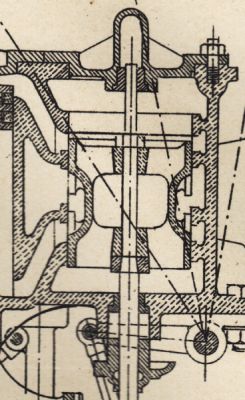
Second I disagree with you that the piston should be fixed at the valve rod and true guided by this bushes. If you look at the drawing above, you can see that the taper on the valve rod is a separate part. This was only done to fix the piston without increasing the upper diameter to much or using a thread. In Emmas engine I am using a "free floating" piston which is guided like a D-valve and aligns itself in the sleeve. This eliminates all impreciseness of the bush alignment, the valve rod or the location of the top cover (which contains the top bush) after several inspections.
In this way the piston will find its way by itself inside of the sleeve and stay in the designed clearance (tight fit with no partial wear) for long.
Rainer
www.steamboating.de
www.steamboating.de
-
gondolier88
- Full Steam Ahead
- Posts: 290
- Joined: Fri Jun 18, 2010 8:54 pm
- Boat Name: No Boat Yet
Re: First core bockes
Rainer,
1- On a second look, yes, they would certainly appear to be push-fit bushes.
2- The taper is a separate collar to give infinite scope for aligning the valve on the rod, however, what would appear to be a thread and nut at the top of the rod would have secured the valve rigidly on the rod.
I agree that to get the gland, valve bore, valve on rod, top bush and top cover concentric would be one hell of a job, but not impossible, and of course, this type of fitting work is what the end-of-line fitters were for, back when time and labour could be charged to the customer without question.
Greg
-
Rainer
- Full Steam Ahead
- Posts: 306
- Joined: Sun Nov 22, 2009 5:42 pm
- Boat Name: Emma and Molly
- Location: Hannover, Germany
- Contact:
Emergency call
mission completed
Last edited by Rainer on Thu Dec 20, 2012 10:34 pm, edited 1 time in total.
Rainer
www.steamboating.de
www.steamboating.de
Re: First core bockes
Rainer:
Miss Ann is going looking for the issue. Hopefully we'll get it to you by Weinachtstag. I sent a separate email for your address.
Miss Ann is going looking for the issue. Hopefully we'll get it to you by Weinachtstag. I sent a separate email for your address.
Steve
-
Rainer
- Full Steam Ahead
- Posts: 306
- Joined: Sun Nov 22, 2009 5:42 pm
- Boat Name: Emma and Molly
- Location: Hannover, Germany
- Contact:
Re: First core bockes
Mission completed - Thanks a lot for solving this problem!S. Weaver wrote:Rainer:Miss Ann is going looking for the issue.
Rainer
www.steamboating.de
www.steamboating.de
-
Rainer
- Full Steam Ahead
- Posts: 306
- Joined: Sun Nov 22, 2009 5:42 pm
- Boat Name: Emma and Molly
- Location: Hannover, Germany
- Contact:
LP Zylinder bore
Today I rough machined the LP cylinder bore. I did it the old fashioned way with a boring head on the manual mill. Actual diameter is 97,2 mm (3.80 inch). For the rough machining I used a feed of 0.3 mm per revolution. For the following fine milling I will use 0,03 mm (0.0012 inch) feed per revolution or better. Ready machined diameter should be 98 mm (3.85 inch).
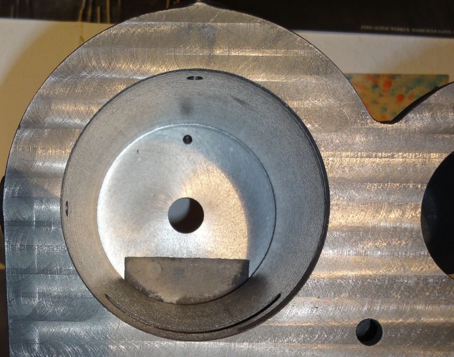
The bottom is already finished with a depth of 112 mm (4.4 inch). Watch the nice and accurate core positioning of the steam canal at the bottom. The little round thing at the canal bottom left is a chaplet (core support). If you have a close look at the picture you also can identify a second chaplet at the right. At the bottom top (on this picture) you can identify two little bright points (left and right from the drain bore). This are two more chaplets - but this were cut right through while machining the cylinder bottom.

picture from wikipedia
http://en.wikipedia.org/wiki/Core_%28manufacturing%29
Here a "J" - type chaplet was used

picture from wikipedia
http://en.wikipedia.org/wiki/Core_%28manufacturing%29
The bottom is already finished with a depth of 112 mm (4.4 inch). Watch the nice and accurate core positioning of the steam canal at the bottom. The little round thing at the canal bottom left is a chaplet (core support). If you have a close look at the picture you also can identify a second chaplet at the right. At the bottom top (on this picture) you can identify two little bright points (left and right from the drain bore). This are two more chaplets - but this were cut right through while machining the cylinder bottom.
picture from wikipedia
http://en.wikipedia.org/wiki/Core_%28manufacturing%29
Here a "J" - type chaplet was used
picture from wikipedia
http://en.wikipedia.org/wiki/Core_%28manufacturing%29
Rainer
www.steamboating.de
www.steamboating.de