They way I have seen these set up, pulling aft on the lever, turns to starboard. So the lever is like the top of a steering wheel. as you have it drawn. It's a lot easier to do with a push and pull cable and they are very inexpensive on Ebay.
"In the moment I try to simulate the tiller or better stick stearing by (with? in? english wording please) CAD."
With or In
Americanized English version "I am drawing a simulation in CAD of the lever steering system."
I always understand your posts, no problem.
If you put a lever on the port side, run the gray shaft to the other side, then flip the brown arm over 180 degrees, this will keep a right hand or clockwise motion turning to starboard on both levers. Or attach the blue arm below the pivot in the red arm.
A wheel could be attached to both sides to actuate the red arm with a long slot in the arm, a pin on the wheel and the wheel mounted on a separate pivot.
-Ron
Re: First core bockes
Posted: Fri Apr 05, 2013 12:21 am
by S. Weaver
You might want to use tensioned, non-stretch rope as is used with halyards. Rope or mechanized as you have it will eliminate the slop of a cable system. There was an article recently in Wooden Boat about vertical tiller/rope systems: Bryan, Harry, author and illustrator: "Rope Steering for Powerboats," 227:48
Re: First core bockes
Posted: Fri Apr 05, 2013 8:28 am
by Albert
Hi Rainer,
Here my suggestion: dimension the length of the steering lever such that it would comfortably work if used as a normal tiller. Then, dimension the different transmission levers such that for the max. rudder angle (36 degrees to either side) the corresponding steering-lever deflection is also 36 degrees. This will render a "natural feeling" when steering the boat.
Albert
Re: First core bockes
Posted: Sun Apr 07, 2013 7:54 pm
by Rainer
Mike wrote:"... am much quicker with a pencil and paper.
Hy Mike,
I even don't know how to sharpen a pencile )
Re: First core bockes
Posted: Sun Apr 07, 2013 10:25 pm
by PatJ
If the steering setup you have requires too much effort to turn, you could add rudder surface forward of the rudder pivot point, which would allow you to turn the boat with less effort.
I piloted a boat one time, and it required a heavy force to turn, but that is not necessary and not desirable.
I did it!
Posted: Tue Apr 09, 2013 6:18 pm
by Rainer
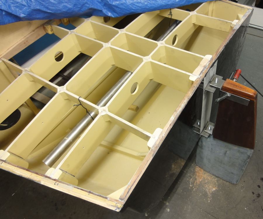
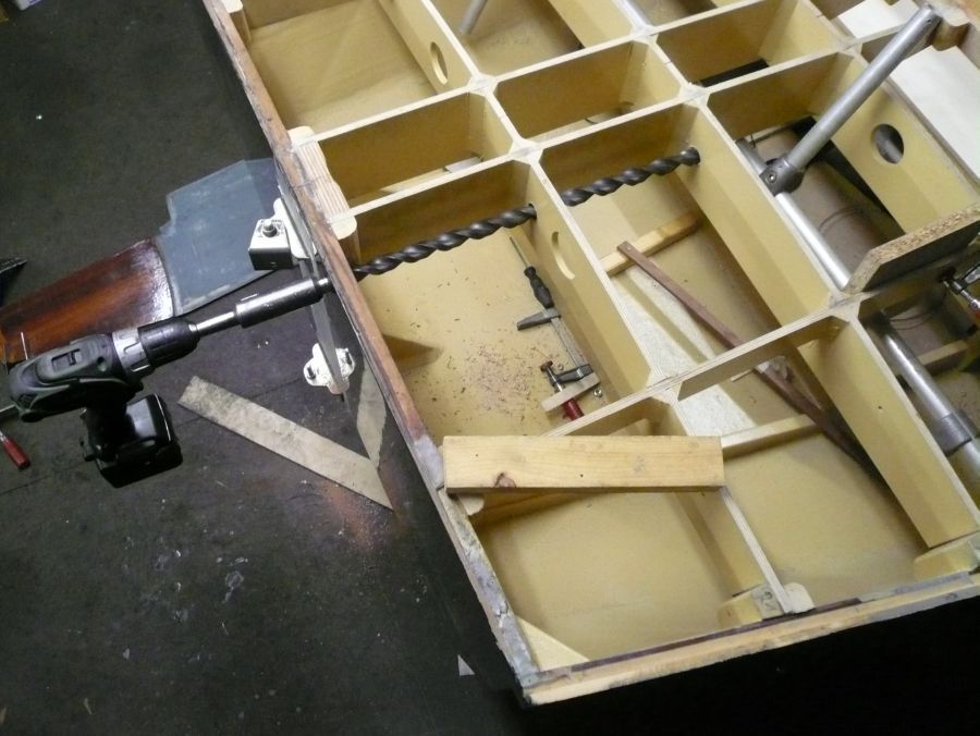
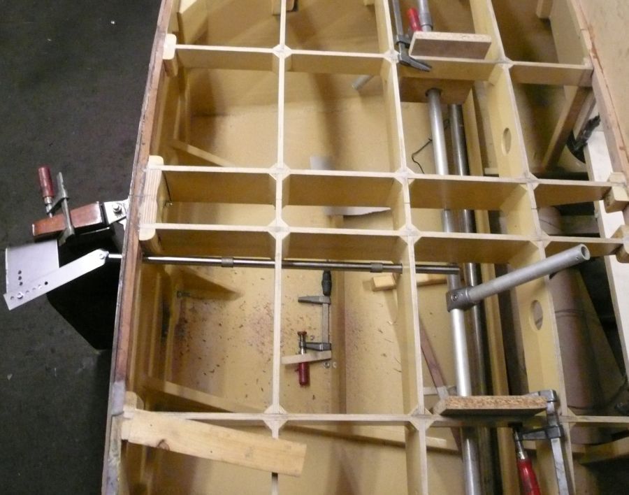
I did it - bored 4 holes into the hull.
All this is a quick and dirty setup to verifying the geometry. The angle plates are from VA already but not in the final shape.
Maybe to much distance between transom stern and rudder?
60 mm here - could go to 50 mm?
Re: First core bockes
Posted: Wed Apr 10, 2013 3:57 pm
by Lopez Mike
A general rule is that the center of lift for common foils is 25% of the chord (front to back width). I once made a new rudder for a sailboat with the center of rotation at 20% and there was very little feel (feed back) to the steering. This was not good on a sailboat. I don't know if it would be a serious problem on a steam launch.
Mike
Re: First core bockes
Posted: Wed Apr 10, 2013 5:20 pm
by Rainer
Mike wrote:... once made a new rudder for a sailboat with the center of rotation at 20% and there was very little feel (feed back) to the steering. This was not good on a sailboat. I don't know if it would be a serious problem on a steam launch...
Hello Mike
Yes, I fixed the design today with 20% also. I agree with you that I should not go to more than 20%.
Hope that this is no problem on a steam boat because you don't have to feel the wind or surf down the waves with a sensitive hand. If this gives a bad/not nice feeling with my boat, I could place some shims between ruder and hinge to end maybe with 15%.
Let's wait and see what's nature will tell us...
Rudder
Posted: Wed May 15, 2013 5:38 pm
by Rainer
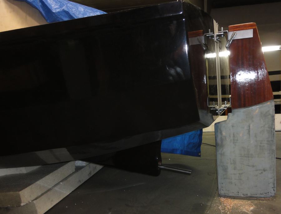
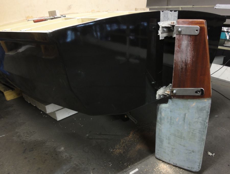
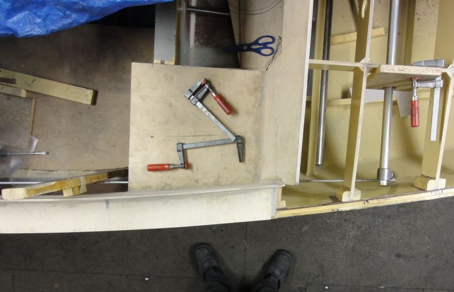
Today the rudder got it's final fitting:
Also the arrangement of levers slowly find it's way to the front.
Here as a temporary setup to test the geometry.
steering gear
Posted: Fri May 24, 2013 5:07 pm
by Rainer
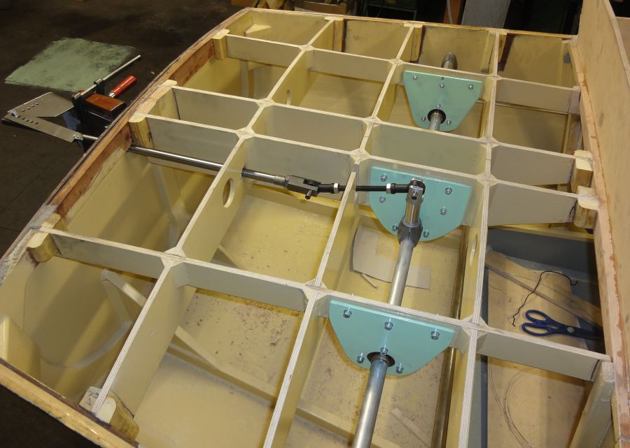
Some more levers...
Bearing brackets from two plates of 6 mm plywood each. Bushings self made from plastic. Bronze jackets glued to the aluminum rod to akt as sliding surface.