Thank You!S. Weaver wrote:Nice!
First core box
-
Rainer

- Full Steam Ahead

- Posts: 306
- Joined: Sun Nov 22, 2009 5:42 pm
- Boat Name: Emma and Molly
- Location: Hannover, Germany
- Contact:
 Re: First core boxes
Thank You!gondolier88 wrote:Your work is inspiring to say the least.
Greg, this was only to irritate the Chinesegondolier88 wrote:One question- your last picture shows the ports going into the cylinder- yet the bottom port is well above (50mm?) what would appear to be the bottom of the cylinder- why is this?Greg
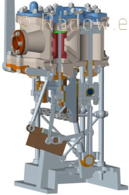
You have to turn your head or monitor about 180° to see the big end as Top Core Mark. Have a look at this drawing. Btw. all free space between the colored cores and the brown cylinder represents the removed material by machining.
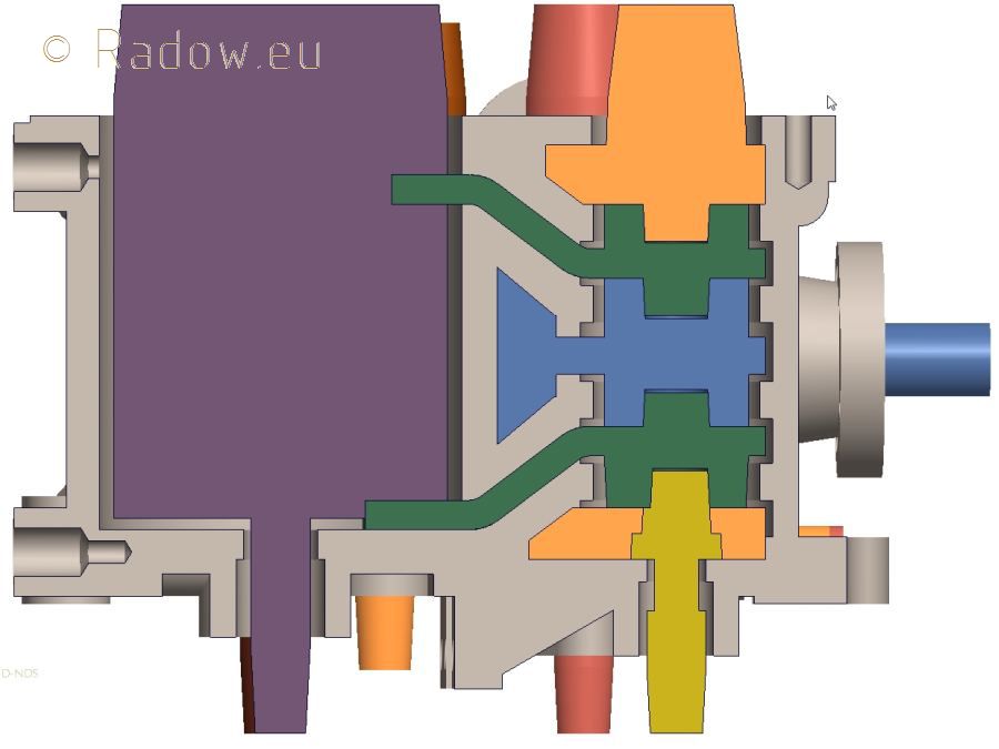
The smal tube represents the piston rod. The original from 1910 and my model has a close casted bottom. More difficult to machine OK - but it also has some advantages. You don't have to machine the lid (good english word in this case? Please help a German) and the threads for it's screws - you don't have to tighten it. You save a lot of space at the cylinder bottom to realize a compact design!
Rainer
www.steamboating.de
www.steamboating.de
-
Rainer
- Full Steam Ahead
- Posts: 306
- Joined: Sun Nov 22, 2009 5:42 pm
- Boat Name: Emma and Molly
- Location: Hannover, Germany
- Contact:
Great News!
Hello All,
this weekend I have build all test cores. Everything fits together. No mistakes in core box design and machining - great moment...
Base with HP cylinder at the right and LP cylinder at the left. Both Bottom ports and the bottom part of the three-part receiver mounted also.
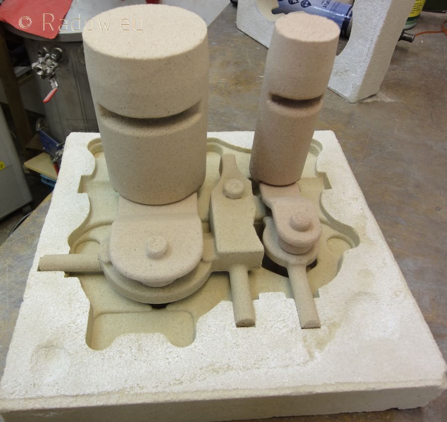
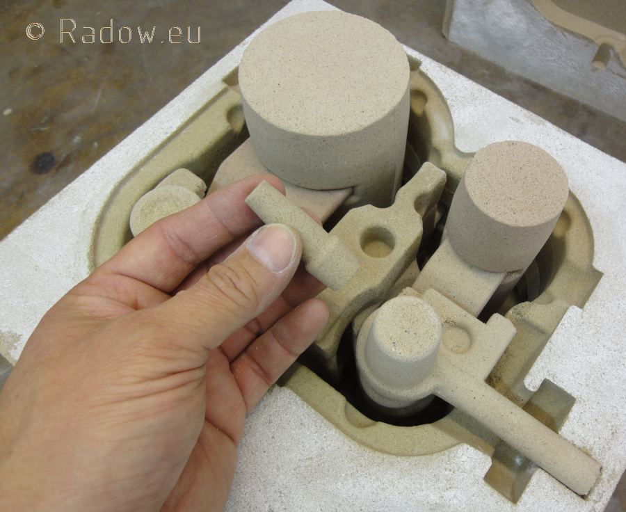
Some "seconds" later. Fitting the last core. OK this are only test cores - everything will go into the dump later. But it is a good way to verify the design and to show the concept at the foundry.
And the best news are: <- where is this link comming from? It wasn't me!
- I brought everything to the foundry today already. They were happy to see me with this molds and core boxes. Hopefully I hold one cylinder made in cast iron in my hands within the next 2 weeks
this weekend I have build all test cores. Everything fits together. No mistakes in core box design and machining - great moment...
Base with HP cylinder at the right and LP cylinder at the left. Both Bottom ports and the bottom part of the three-part receiver mounted also.
Some "seconds" later. Fitting the last core. OK this are only test cores - everything will go into the dump later. But it is a good way to verify the design and to show the concept at the foundry.
And the best news are: <- where is this link comming from? It wasn't me!
- I brought everything to the foundry today already. They were happy to see me with this molds and core boxes. Hopefully I hold one cylinder made in cast iron in my hands within the next 2 weeks
Rainer
www.steamboating.de
www.steamboating.de
Re: First core boxes
Love to help the landsman. The "good english word" is head; the lower cylinder head is integral with the cylinder casting. That is an interesting design. It has been educational to see this engine go from historical prototype to concept to the foundry. Your pattern-making is inspiring!Rainer wrote:... The original from 1910 and my model has a close casted bottom. More difficult to machine OK - but it also has some advantages. You don't have to machine the lid (good english word in this case? Please help a German) and the threads for it's screws - you don't have to tighten it. You save a lot of space at the cylinder bottom to realize a compact design!
Steve
-
gondolier88

- Full Steam Ahead
- Posts: 290
- Joined: Fri Jun 18, 2010 8:54 pm
- Boat Name: No Boat Yet
Re: First core boxes
Thank you Rainer,Rainer wrote: You have to turn your head or monitor about 180° to see the big end as Top Core Mark. Have a look at this drawing. Btw. all free space between the colored cores and the brown cylinder represents the removed material by machining.
The smal tube represents the piston rod. The original from 1910 and my model has a close casted bottom. More difficult to machine OK - but it also has some advantages. You don't have to machine the lid (good english word in this case? Please help a German) and the threads for it's screws - you don't have to tighten it. You save a lot of space at the cylinder bottom to realize a compact design!
It is so unusual to see someone putting so much effort onto reproducing a copy of an engine, integral cylinder bottom covers were a detail of high end engines- you are right in saying that there is less work, but you need an accurate jig for the cylinders and only get one chance at boring the gland- not that this would be a problem for you!
Out of interest, did the original engine have conical pistons?
Greg
-
Rainer
- Full Steam Ahead
- Posts: 306
- Joined: Sun Nov 22, 2009 5:42 pm
- Boat Name: Emma and Molly
- Location: Hannover, Germany
- Contact:
 Why this machine ...
Yes I am asking this myself too - why not doing some high tech stuff - that's why I started building a RepRap 3D printer and a CNC mill toogondolier88 wrote:It is so unusual to see someone putting so much effort onto reproducing a copy of an engine
This engine was the only old German small engine design I found in the accessible archives. So I thought it would be worth to reproduce it. OK this is not the best/latest design for a steam engine -and OK it is also part of a copies of English engines because "we" Germans came in 1880 to England like the Chinese to Europe today to copy technical stuff.
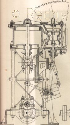
Have a look at this original drawing - not really conical...gondolier88 wrote:Out of interest, did the original engine have conical pistons?
To reveal the secrets of the cast and core design of this engine from only a small drawing was much fun. It was like a time travel. What would the old designers think about today's engineering methods - but we still cast in sand - but in by hand. But also this will change because of this:
Unfortunately this is some 1000 Euro per cast..
But there is light at the end of the exhaust pipe (if you don't condense)! After building the RepRap 3D printer I found this printing method - maybe someone (me) could convert it to print sand cores also cheap - maybe in 20 years?
http://www.thingiverse.com/thing:27794
I am not sure yet how to start machining it. I have to hold the cast iron part in my hands first. I am curious of how it comes out. All four glands, the fife retainer for the support columns and the two slideway rests have to be at the precise position - but we have the today's advantage of CNC machining.gondolier88 wrote: integral cylinder bottom covers were a detail of high end engines- you are right in saying that there is less work, but you need an accurate jig for the cylinders and only get one chance at boring the gland
Additional I did not start to build the engine base and the crank shaft jet - so I could correct this if something goes wrong with the cylinder block.
Rainer
Rainer
www.steamboating.de
www.steamboating.de
-
fredrosse

- Full Steam Ahead
- Posts: 1930
- Joined: Fri Nov 20, 2009 5:34 am
- Boat Name: Margaret S.
- Location: Phila PA USA
- Contact:
Re: First core bockes
"Unfortunately this is some 1000 Euro per cast."
This method is so fantastic, I think $1000 Euro per cast is a real bargain, much lower than the work to produce this with the old methods.
Your picture of the original engine is only 20k, and you can go up to 250k with a single picture. Would it be possible to post the same picture with the higher resolution?
Thanks again for the great innovation you have brought to the forum.
-
Rainer
- Full Steam Ahead
- Posts: 306
- Joined: Sun Nov 22, 2009 5:42 pm
- Boat Name: Emma and Molly
- Location: Hannover, Germany
- Contact:
 Re: First core boxes
OK - translation mistake or mistake in reading what you like to read "some 1000 Euro" in this case does not mean around 1000 Euro but x time 1000 Euro...fredrosse wrote:"Unfortunately this is some 1000 Euro per cast."
This method is so fantastic, I think $1000 Euro per cast is a real bargain, much lower than the work to produce this with the old methods.
But I think this will change some days.
Even with my method you have to calculate with 1 < x < 2 for mold material and the guys in the foundry for the first part - not including my time to design and machine the molds.
Rainer
Rainer
www.steamboating.de
www.steamboating.de
-
gondolier88
- Full Steam Ahead
- Posts: 290
- Joined: Fri Jun 18, 2010 8:54 pm
- Boat Name: No Boat Yet
Re: Why this machine ...
Hi Rainer,Rainer wrote: This engine was the only old German small engine design I found in the accessible archives. So I thought it would be worth to reproduce it. OK this is not the best/latest design for a steam engine -and OK it is also part of a copies of English engines because "we" Germans came in 1880 to England like the Chinese to Europe today to copy technical stuff.
Have a look at this original drawing - not really conical...gondolier88 wrote:Out of interest, did the original engine have conical pistons?
Rainer
The picture of the original drawing confirms something I wondered about- I notice that the cylinder has an indented gland that encroaches into the cylinder, with a corresponding piston underside shape. The top of the piston is conical (although not much in this design), and slopes towards the cylinder drains.
Both these features are necessary on a piston valve engine as the valve cannot lift to release condensate or to relieve for priming- you will notice that the top steam inlet port and drain outlet are in-line with each other and at no point, even at TDC, are the drain and the port completely covered- allowing for an element of safety if priming should occur.
Comparing your 3D cutaway side by side it would appear that at TDC the engine drain is above the inlet port and only just level with the piston top- allowing for dwell time, there will be a very small chance for condensate to exit the cylinder, and at TDC, should priming occur, the piston valve could lock hydraulically, at best, bending your valve gear, at worst possibly cracking your block.
One detail that I have seen on piston valve engines is the use of overpressure release valves that are set above the boiler working pressure and safeguard against hydraulic locking.
It could be that I've read your 3D drawing wrong.
Greg
-
Rainer
- Full Steam Ahead
- Posts: 306
- Joined: Sun Nov 22, 2009 5:42 pm
- Boat Name: Emma and Molly
- Location: Hannover, Germany
- Contact:
Re: Why this machine ...
Hello Greg,gondolier88 wrote:Comparing your 3D cutaway side by side it would appear that at TDC the engine drain is above the inlet port and only just level with the piston top- allowing for dwell time, there will be a very small chance for condensate to exit the cylinder, and at TDC, should priming occur, the piston valve could lock hydraulically, at best, bending your valve gear, at worst possibly cracking your block.
first of all thank you for your close look at my drawing and for your answer. This will help me to go deeper into this matter. In the moment I have focused on the cylinder casting. It is the only detailed part now because it is the most complex I ever did... In the moment I try to fine detail the other cast parts - but yes, I also should focus on the piston.
After your comment I got into the simulation section and cranked the engine to TDC:
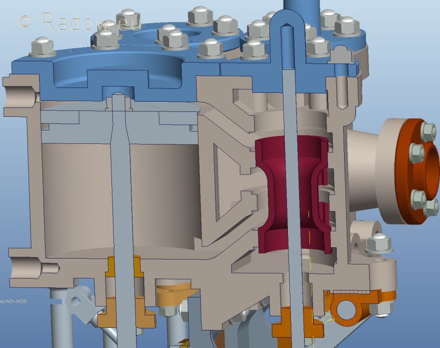
And yes you are right that the inlet and the drain are not in-line what would be better. And yes, in the moment the pisotn top is lower than the drain. The port is 8 mm high and the piston goes 3 mm over the lover port edge. So the condensate will run to the piston valve but not to the drain... Should remember this whyle doing the end design of the piston and the cylinder head. Now with your hints I will take care of this issue. I can make the piston maybe 2 mm thicker and bore the drain with a bigger diameter. Don't know if I will give the piston a slightly conical shape...
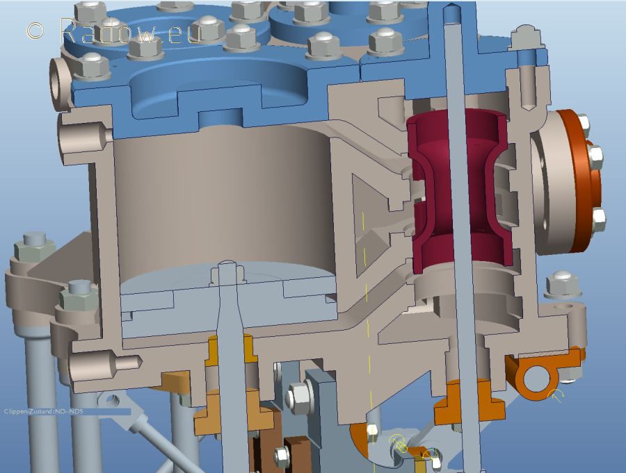
Just to complete this, here the BDC view:
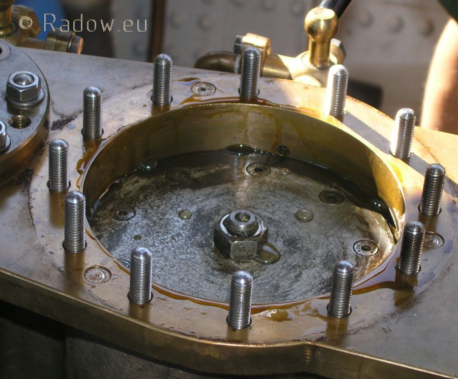
As you might know, my steam boat Emma has also one piston valve. Here you can see how I designed/build the piston, the port and the drain. This works for me - never had trouble with water hammering - I ever planed to install an overpressure release valve - never build one. But you might be right that for this smaller engine such a "fuse" would be a good feature!gondolier88 wrote:One detail that I have seen on piston valve engines is the use of overpressure release valves that are set above the boiler working pressure and safeguard against hydraulic locking.
Last edited by Rainer on Wed Sep 12, 2012 9:59 pm, edited 1 time in total.
Rainer
www.steamboating.de
www.steamboating.de