Page 3 of 6
Re: Designing a new engine for a big(ger) boat...
Posted: Mon Jan 07, 2013 5:05 pm
by steamboatjack
Bart,
It's great to see some new ideas and people willing to spend time designing a very worth while project, well done!
Regards
Jack
Re: Designing a new engine for a big(ger) boat...
Posted: Sun Jan 13, 2013 6:37 am
by Lopez Mike
I spent a bit of time as deck hand for Al Giles of Olympia, WA on his second and last steamer, Echo. He started with a Disney engine and after a number of embarrassing dock incidents due to unpredictable failures to reverse, he re-powered with an I.C. engine.
So what I'm saying is, pay a sufficient attention to this problem. I have forgotten exactly what the problem was but that Al, an experienced and thoughtful man, felt that he couldn't correct the problem without a major redesign of the engine.
Mike
Re: Designing a new engine for a big(ger) boat...
Posted: Sun Jan 13, 2013 6:43 pm
by barts
Lopez Mike wrote:I spent a bit of time as deck hand for Al Giles of Olympia, WA on his second and last steamer, Echo. He started with a Disney engine and after a number of embarrassing dock incidents due to unpredictable failures to reverse, he re-powered with an I.C. engine.
So what I'm saying is, pay a sufficient attention to this problem. I have forgotten exactly what the problem was but that Al, an experienced and thoughtful man, felt that he couldn't correct the problem without a major redesign of the engine.
Mike
Yes, getting reliable reversing and designing for single handed operation are important for the boat to be useable. Some of my thoughts in this area include:
- Sufficient cut-off in full gear to permit starting the engine from any position. Adjusting the overlap of two cams make it possible to go from 75% to 5% cut-off while still maintaining reasonable valve travel.
Increased engine clearance available when maneuvering; this decreases compression on the uniflow engines and makes it possible to operate the engine at lower intake pressures - with a throttle, in other words. The only real trick here is to design this such that it doesn't materially affect clearance when not in use.
Steam eductor to generate full vacuum (~26 inches Hg) at zero rpm when maneuvering. Allan Gregg uses this on his SL Lorraine to good effect.
Automatic relief of excess cylinder pressure with the intake poppet valves being forced open by the pressure difference.
The goal is to be able to go from forward to reverse and back with the engine turning. Once we're underway, the clearance can be reduced, the cut-off lowered to efficient values, the throttles opened and the eductor turned off.
I've been spending some time getting familiar (way too early to say good) with SketchUp, and designing some of the cylinder head details; I last used CAD systems in the 1980s so things are a little slow.
- Bart
Re: Designing a new engine for a big(ger) boat...
Posted: Tue Feb 05, 2013 3:14 am
by fredrosse
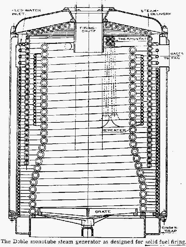
As to the boiler for your new boat, seems like a top firing boiler would be desirable. A couple of sketches where the Capitan can fire with either a cabin style boat or a tug style boat, boiler about 3 ft dia x 4 ft high:


Re: Designing a new engine for a big(ger) boat...
Posted: Tue Feb 05, 2013 3:24 am
by fredrosse
Re: Designing a new engine for a big(ger) boat...
Posted: Wed Feb 06, 2013 2:01 am
by fredrosse
Within this topic I could not find the Uniflow Engine Poppet Admission Valve that was used on the Domestic Heat-Power Module project. If it is posted somewhere here already, please forgive the re-posting of the drawing.
This valve provides sharp cutoff, as well as leakproof seating, with no lubrication, and also keeps the return spring out of the hot steam space. The valve stem packing, spring, and keeper used is the same as the counterflow engine posted previously within this topic. Perhaps the best feature of this valve is that it survived with about 4000 hours of 24/7 running, although with moderate steam conditions (150 PSIA, Saturated), not with the high temperatures you anticipate.

This was a single acting engine, but on a double acting engine it would have to be modified in arrangement to miss the piston rod and packing. With high pressure steam and early cutoff, this valve could be much smaller in relation to the cylinder shown on the drawing.
Re: Designing a new engine for a big(ger) boat...
Posted: Wed Feb 06, 2013 10:54 am
by Albert
Hi Bart,
Poppet-valve engine? Here you have a high-tech, high-quality one (although with the charm of a sterilization machine…). And because a normal boiler would rob you of the needed space for extended voyages, what about a flat, underfloor boiler? A really special design installed on the same boat.

Happy designing
Albert
Re: Designing a new engine for a big(ger) boat...
Posted: Tue Nov 26, 2013 5:53 am
by barts
I'm still working on this; last winter turned into a marathon Airstream trailer rebuild. That's pretty much done, so w/ more time I'm getting back on the big engine design. I have worked out some more details.
* Twin cylinder double acting engine using cylinder liners from 71 CID Detroit Diesel.
- This gives me more displacement, and lets me use 250 PSI saturated steam - nicer to be around.
- Liners are readily available, as are rings.
- Bottom of liner gets trimmed slightly so distance from end of liner to ports is the same top and bottom.
* Each cylinder has two weldments, top and bottom. All four bolt to a single aluminum exhaust belt plate that ties
cylinder together and provides exhaust plumbing. Engine cylinder assembly is supported via 8 1" rods connecting
center exhaust belt to engine bedplate; this lets engine cylinders expand and makes adjusting packing easier.
* Slow speed reversibility provided by opening valves for additional clearance. Drains come off the clearance chambers.
May be able to use large ball checks between cylinder and clearance chambers as valves; they are closed by admitting steam into chambers.
Same technique can be used for drains; these are either routed to steam or to vacuum.
* Each cylinder head contains 30 CID volume for intake steam; poppet valve opens to release steam from head into cylinder bore.
* Poppet valves are standard small engine parts. They are actuated by bell crank rocker arms, and are driven by a pair of camshafts ala Skinner running horizontally aside of the two cylinders at the exhaust belt. Phase angle of cams is controlled by helical pitch sleeves like a Semple reversing gear. Max cut-off is +50% to facilitate self starting.
* Crankshaft is built up using Rolly Evan's pinch bolt design. Connecting rod bearings at top are needle bearings; mains and big ends are rolling contact bearings of some sort.
* roller cross head.
* Engine bedplate is a weldment of rectangular steel tubing. Bearing housings bolt to top of bed plate.
I'll try and get some sketches posted.
- Bart
Re: Designing a new engine for a big(ger) boat...
Posted: Tue Nov 26, 2013 10:38 pm
by fredrosse
Sounds like a good design setup, the product of much thought plus many nights considering many options and tradeoffs.
The center exhaust assembly, how will the seal between the cylinder outside diameter and the aluminum part be made? O-rings, Gaskets, Hi-temp caulk like RTV automotive gasket maker, or...??
It is recommended to stress relieve any engine weldments, that makes machining and fabrication alignments less of a nightmare. The costs and time to have this done commercially is lower than one might think. It can be done in the home shop, but not without much preparation and labor.
Re: Designing a new engine for a big(ger) boat...
Posted: Tue Nov 26, 2013 11:40 pm
by barts
fredrosse wrote:Sounds like a good design setup, the product of much thought plus many nights considering many options and tradeoffs.
The center exhaust assembly, how will the seal between the cylinder outside diameter and the aluminum part be made? O-rings, Gaskets, Hi-temp caulk like RTV automotive gasket maker, or...??
It is recommended to stress relieve any engine weldments, that makes machining and fabrication alignments less of a nightmare. The costs and time to have this done commercially is lower than one might think. It can be done in the home shop, but not without much preparation and labor.
For seals, I've had very good luck with a small groove or indent in one part and then coating w/ high temp RTV. This basically forms a 450 F capable O-ring in place. I had planned to stress relieve the weldments. The cylinder weldments are basically 5" diameter schedule 120 pipe about 4" long w/ a round flange on top and a square flange on the bottom, all welded w/ 7018. I'd planned to just heat the weldments to 1200 F or so w/ a weed burner and bury them in vermiculite like I do when blacksmithing. I also have a pottery kiln I can use for this purpose and just leave 'em in there while it cools.
Thanks for the comments... much of this has been a real head scratcher. I'm still weighing the various bearing choices... needle bearings would be ideal, but there's no axial location, and the combined bearings that provide this are quite expensive. Using the sides of the rods against the crank cheeks requires steady lube. Deep groove ball bearings will definitely work, and they're relatively inexpensive and come complete w/ seals, which makes them simple to use. They are fairly large on the OD, though, but they look like my best bet so long as the load ratings are sufficient. Tapered roller bearings are quite rugged, but designing in end play adjustment is fiddly. Cylindrical roller bearings have very impressive load ratings and prices to match - and need seals, too.
I looked at babbit bearings, but the peak loads are way past what non-pressure lubed babbit wants to handle. In any case, oil control is a pita, and with the engine in the living quarters in the boat I want a design that doesn't reek of machine oil.
- Bart