Page 21 of 22
Pattern Mill
Posted: Fri Feb 28, 2014 12:00 am
by Rainer
OK, here is how I did it tonight:
I have build a fixture for both sides of the gate. It's just a L-iron with a M3 threat (screw with diameter 3 mm = 0.12 inch). A regular M3 threat has 0.5 mm pitch. So one turn lifts it 0.5 mm (0.02 inch) quite fine enough for fine adjustment - especially with a long wrench:
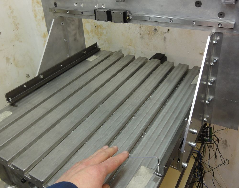
- 2014-02-27.223424-k.jpg (123.93 KiB) Viewed 34191 times
Than came the high tech. The Faro Gage is a 3D hand guided measuring unit which I am using at work for measuring the lathe beds of our customers. It has a display resolution of 0.0001 mm = 0.000004 inch - see the monitor at the right. With this it was done quite easy because the mill bed was made on an high class 5 axis mill and all guidances are new and quite accurate. Only thing is to learn in which direction everything bends while fastening the screws of the mill frame. At least I have no greater deviation than 0.05 mm equal +/- 0.025 mm (0.002 inch or +/- 0.01 inch) on all the distances (365 mm in X, 435 mm in Y) - I think that is quite OK for a pattern mill.
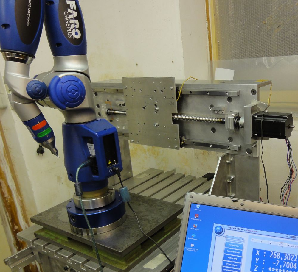
- 2014-02-27.230724-k.jpg (147.58 KiB) Viewed 34191 times
Ready for the first fight at the weekend. Here shown with a diameter 10 mm ball mill (0.4 inch) which here reaches 85 mm out of the chuck (3.35 inch). The spindle motor is the quite common Chinese-Ebay water cooled model with an ER 20 chuck. It should consume 2.2 kw (don't know how much of this ever will reach the endmill

) It is driven by a single phase to 3 phase frequency converter from 6,000 up to 24,000 rpm.
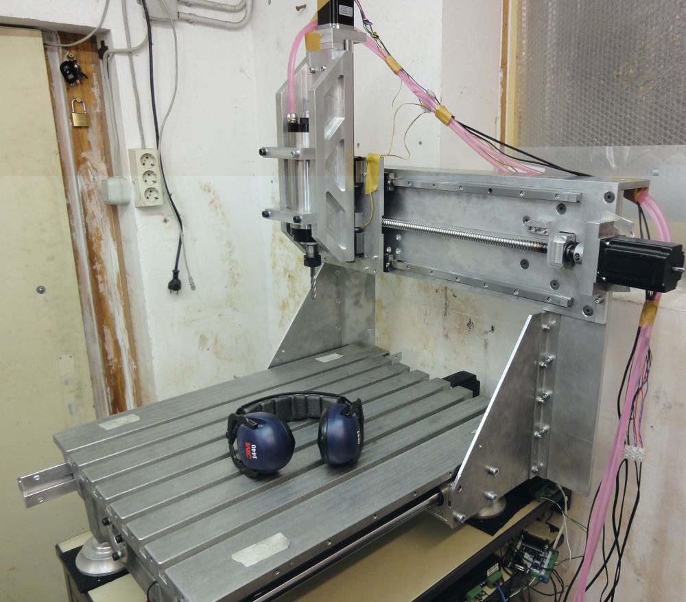
- 2014-02-28.000620-k.jpg (143.69 KiB) Viewed 34191 times
Next will be to build the cable guide and the dust covers...
Pattern Mill
Posted: Fri Feb 28, 2014 11:40 pm
by Rainer
Hello Steamboaters,
no steam and no boat but progress:
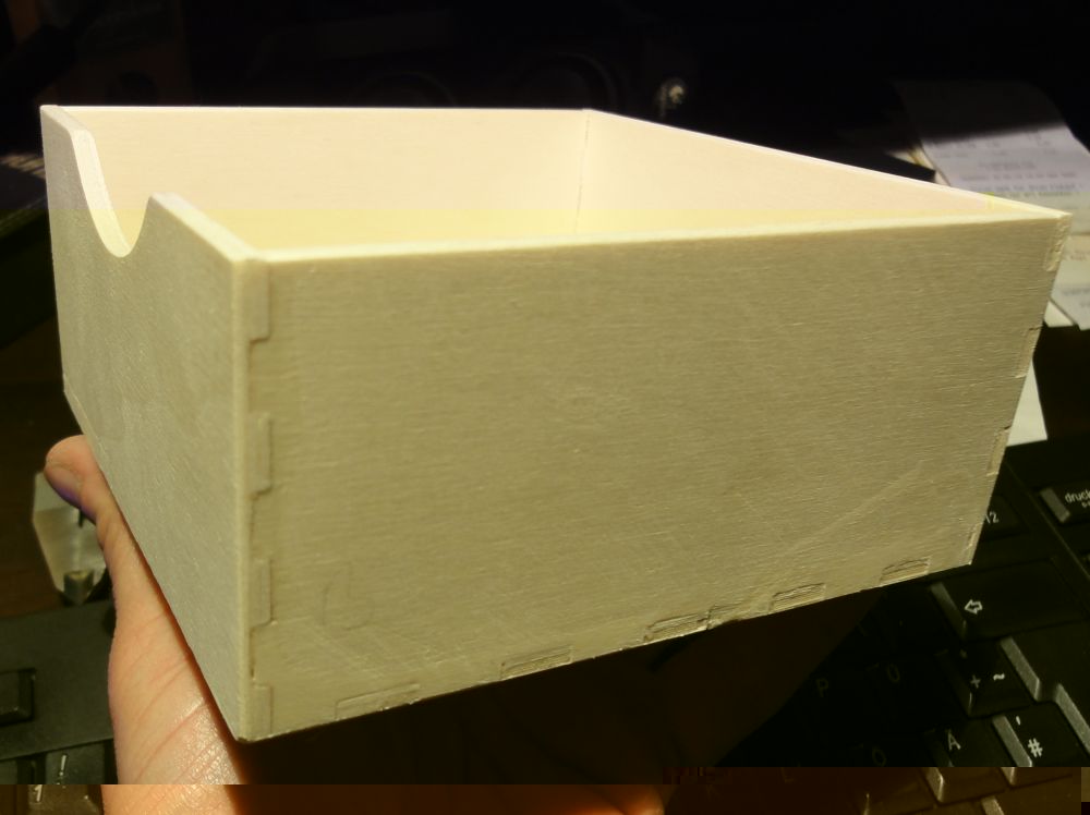
Produced a little wooden box tonight - the first real product on this new mill. There is a free German software which calculates and draws boxes into a dxf file with wooden joints from any dimensions given by the user. From this dxf-file I generated the tool paths:
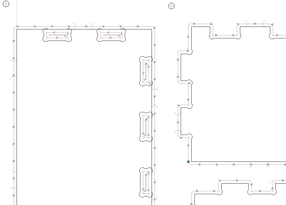
- 2014-02-28.230000.jpg (35.11 KiB) Viewed 34169 times
First is to drill the holes to hold the wood down by screws - its shabby 4 mm (1/6 inch) poplar "plywood". Doing the drilling within the program, you are sure that they are not in the end mills way...
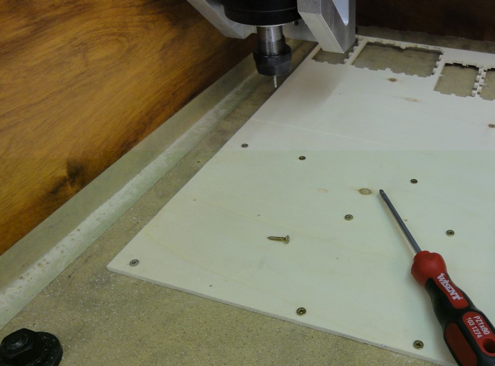
- 2014-02-28.231608-k.jpg (68.71 KiB) Viewed 34169 times
Second is to machine the hidden joints at the front and the back panel. The corners are rounded deeper into the rectangular shape to give clearance space for the joining partners.

- 2014-02-28.231936-k.jpg (60.64 KiB) Viewed 34169 times
Only 3 pictures allowed - goto next post:
Pattern Mill
Posted: Fri Feb 28, 2014 11:50 pm
by Rainer
All parts are fixed with fillets to prevent any damage during the milling process. You can easily cut it out afterwards with a sharp knife.
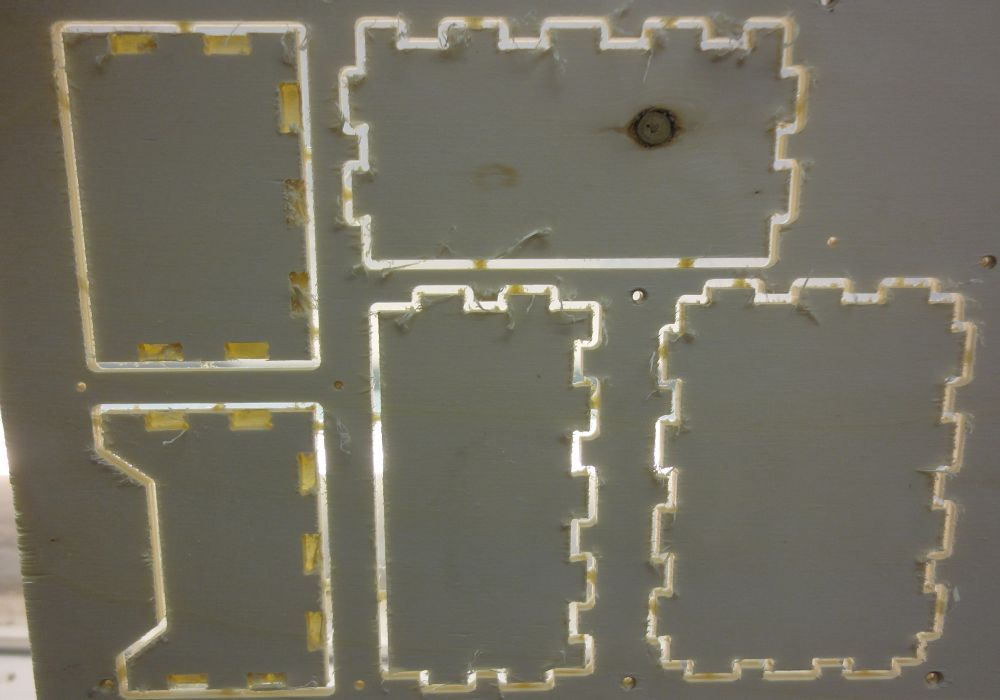
- 2014-02-28.233108-k.jpg (78.35 KiB) Viewed 34169 times
You will need some sand paper if you don't use a wood end mill - as I did...
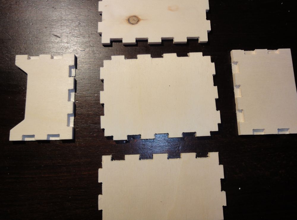
- 2014-02-28.235108-k.jpg (88.4 KiB) Viewed 34169 times
Ready to be used in the "American Girl" dollhouse of my daughter - you have to make your projects also useful for your family...
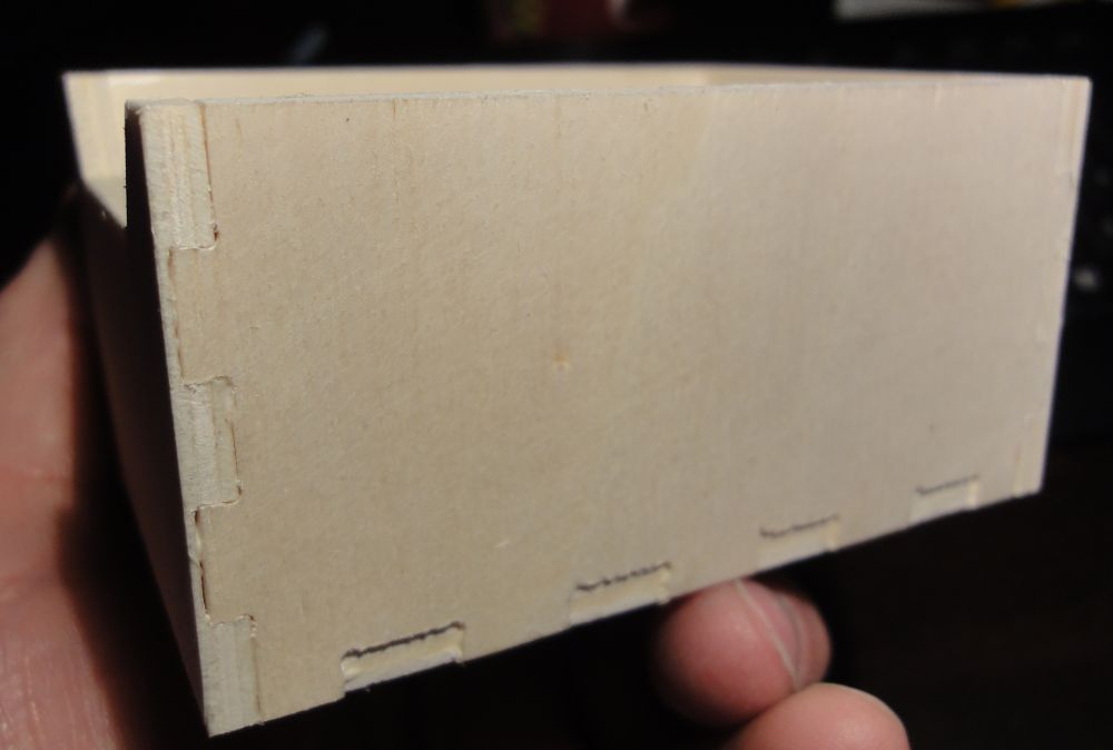
- 2014-03-01.000028-k.jpg (56.3 KiB) Viewed 34169 times
Bottom joints in the given dxf-file are shorter than the plywood width -a bug or a feature???
Next will be some 3D-test-objects
Re: First core box
Posted: Mon Mar 03, 2014 7:43 pm
by PeteThePen1
Well done Rainer
That looks better than 3D printing in plastic. I will be interested to see where you tke it next.
Regards
Pete
Re: First core box
Posted: Tue Mar 04, 2014 11:12 pm
by Rainer
Thanks Pete,
now where all the tools are ready for "chipping" I have to rethink my engine base and make it machinable. After that I have to find the best machining strategy. Base pattern has at least 6 hours machining time.. So it is worth to think about all of this twice. Will do the first test with cheap rigid foam plates - but this also takes this estimated machining time if you don't want to get a melted something after some rapid machining moves...
Changed the length of the tooth in the dxf-file - needs still some more sanding... 5" x 5" x 2.3"
- 2014-03-02.002732-k.jpg (73.99 KiB) Viewed 34130 times
Pumps
Posted: Sat Mar 22, 2014 8:56 pm
by Rainer
I am back at the drawing board...
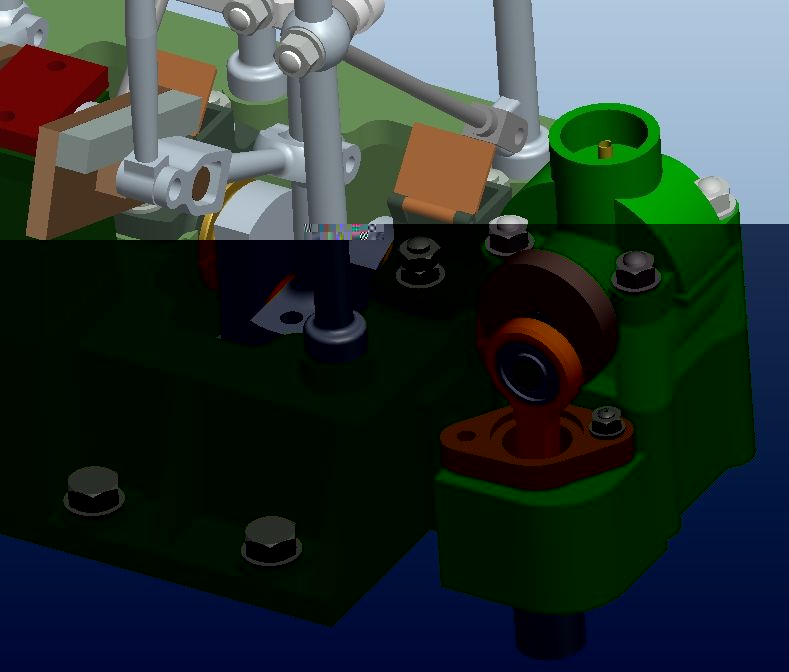
because I don't know anything about the original German pump setup I try to imitate this late Savery pump system:

- 2014-03-22.214002.jpg (108.94 KiB) Viewed 34083 times
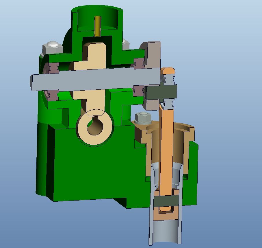
First I choose a worm gear from a catalog and than defined the bore and stroke from the needed feed water amount. I ended up with a 5:1 ratio, a bore of 24 mm (0.95 inch) and a stroke of 22 mm (0.87 inch). My backward calculation secured the dimension of the worm gear. This is my todays layout study for the feed water pump - lots of parts are missing. Vacuum pump will follow later...
- 2014-03-22.214001.jpg (53.54 KiB) Viewed 34083 times
I will play the bad guy and use ball bearings here...
- 2014-03-22.214000.jpg (48.86 KiB) Viewed 34083 times
3d-milling
Posted: Sun Mar 23, 2014 9:16 pm
by Rainer
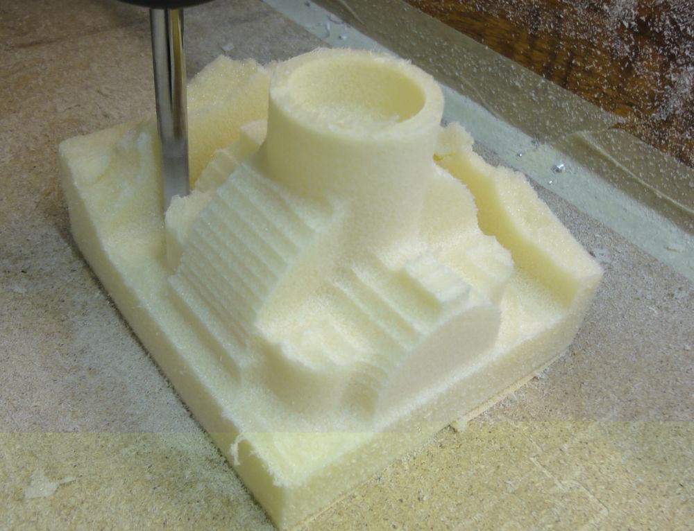
Today I did a test milling of the gear top cover:
Roughening with 8 mm ball mill in 10 mm z-steps. 20% x-Y overlap

- 2014-03-23.205252-k.jpg (129.05 KiB) Viewed 34067 times
Finishing in 3 mm z-steps
- 2014-03-23.205648-k.jpg (117.69 KiB) Viewed 34067 times
Outer dimensions of the part 80 x 80 x 60 mm.
There is space for bigger projects.
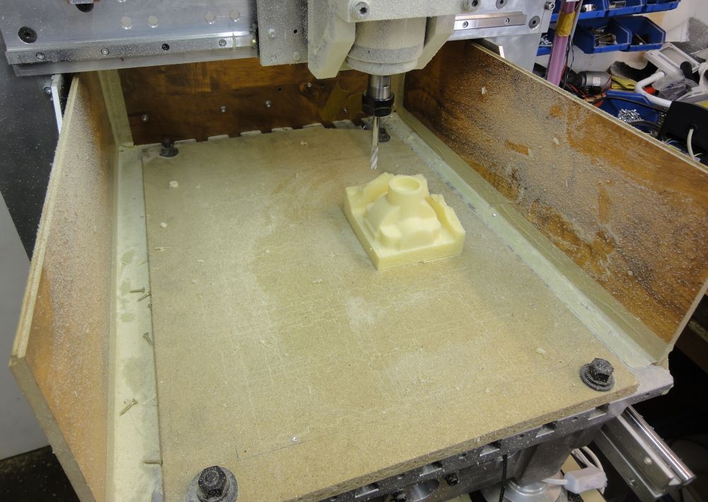
- 2014-03-23.210904-k.jpg (137.82 KiB) Viewed 34067 times
3d-milling
Posted: Sun Mar 23, 2014 9:24 pm
by Rainer
Only 3 pictures allowed per post - so I will contiue here
Residual material milling with 0.5 mm z-steps
Max travel = 2.5 m/min = 40 mm/sec = 1.6 inch/sec - Total milling time from raw material about 30 minute. Will take at least twice as long with the harder material for the molds.
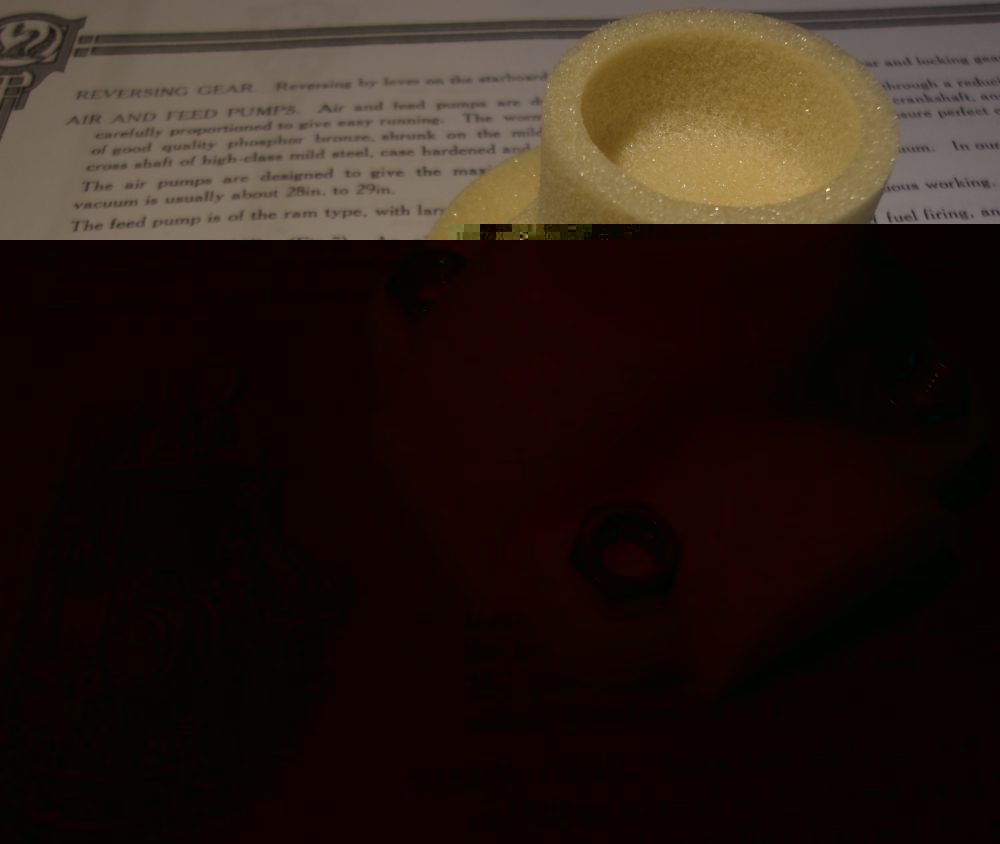
- 2014-03-23.213300-k.jpg (131.92 KiB) Viewed 34066 times
Better than in the CAM preview - residual material is marked gray. Effect was planed for the inner corners. Some other areas could be smoothen by extra milling operations if necessary - but for the first 3D part on my home made CNC-mill with the new CAM software it is quite OK
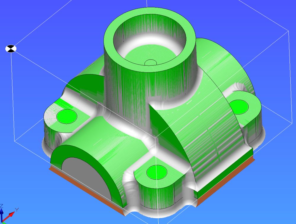
- 2014-03-23.2148.jpg (82.92 KiB) Viewed 34066 times
Re: First core box
Posted: Mon Mar 24, 2014 6:19 pm
by TahoeSteam
Quite OK indeed!
I am very envious of your machinery and ability!
Re: First core box
Posted: Tue Apr 01, 2014 9:13 pm
by PeteThePen1
Great Stuff!
Well done, Rainer. I do like the idea of being able to draw it, program it and then set the machine to make it.
Regards
Pete