gondolier88 wrote: I notice that the cylinder has an indented gland that encroaches into the cylinder, with a corresponding piston underside shape.
I think that feature is mostly to reduce the piston weight by thinning it and still keeping the piston ring section heigh enough by this denting. But yes, it also helps to press the water out of the cylinder...
Re: indented gland
Posted: Wed Sep 12, 2012 10:22 pm
by Mike Rometer
Rainer wrote:Hello Greg,
I have forgotten to comment this
gondolier88 wrote: I notice that the cylinder has an indented gland that encroaches into the cylinder, with a corresponding piston underside shape.
I think that feature is mostly to reduce the piston weight by thinning it and still keeping the piston ring section heigh enough by this denting. But yes, it also helps to press the water out of the cylinder...
.............and reduces the 'unswept' volume of the cylinder to the minimum to take best advantage of the expansion from the steam.
Re: First core bockes
Posted: Thu Sep 13, 2012 2:59 am
by Aheadslow
Beautiful work Rainer. I just love a complex core design. It all looks very well thought out. I can hardly wait to see the castings.
should be a lovely engine when finished,really something to be proud of. Keep up the good work.
Re: First core bockes
Posted: Thu Sep 13, 2012 9:01 pm
by gondolier88
Rainer wrote:Hello Greg,
I have forgotten to comment this
gondolier88 wrote: I notice that the cylinder has an indented gland that encroaches into the cylinder, with a corresponding piston underside shape.
I think that feature is mostly to reduce the piston weight by thinning it and still keeping the piston ring section heigh enough by this denting. But yes, it also helps to press the water out of the cylinder...
Yes, you're right of course, the main reason is to reduce weight, but, as you point out, it also aids ridding the cylinder of condensate. The main reason for making the pistons conical was that they were inherently stronger than flat pistons, meaning they could be made thinner- however, by making them thinner it increased the swept volume of the cylinder- another reason for indenting the gland into the cylinder as Aheadslow points out.
Re. The drain height- you are right, it was difficult to tell the heights from the small 3D drawing, but you should be able to remedy the slight problem.
I'm really looking forward to seeing this block come back from the foundry!
Greg
Re: First core bockes
Posted: Fri Sep 14, 2012 8:03 am
by Johnlanark
This is wonderful Rainier, you are setting an amazing new standard.
Looking back a page, are you saying that you have already built a Reprap machine? I assume that you could use it to make the patterns with core prints, and the core boxes. Or is this still a long way in the future as I think you may be saying to Pat (Steamguy). Best of luck. John
Re RepRap
Posted: Fri Sep 14, 2012 7:14 pm
by Rainer
Johnlanark wrote:Looking back a page, are you saying that you have already built a Reprap machine?
Or have a look how it works on my desktop - printing a herringbone gear
and a vase
Johnlanark wrote:I assume that you could use it to make the patterns with core prints, and the core boxes.
Yes, but I have problems to print big solid parts (bigger than 150 x 150 mm) true to size and without deformation. Additional this printing method produces layers with ABS sausages. The round shape of this builds undercuts make it difficult to get it out of the sand. To prevent this, you have to rework the mold - thats what I like to avoid...
Johnlanark wrote:Or is this still a long way in the future as I think you may be saying to Pat
Future or more money
Re: First core bockes
Posted: Sun Sep 16, 2012 11:05 am
by kno3
It's the first time I see how sand cores etc. are made and I'm following this with great interest. It should become a very nice engine when finished.
By the way, is the valve gear of the Hackworth type? It seems to have a straight slide if I'm not mistaken.
Slideway suspension bar
Posted: Sun Sep 16, 2012 3:27 pm
by Rainer
Hello Forum
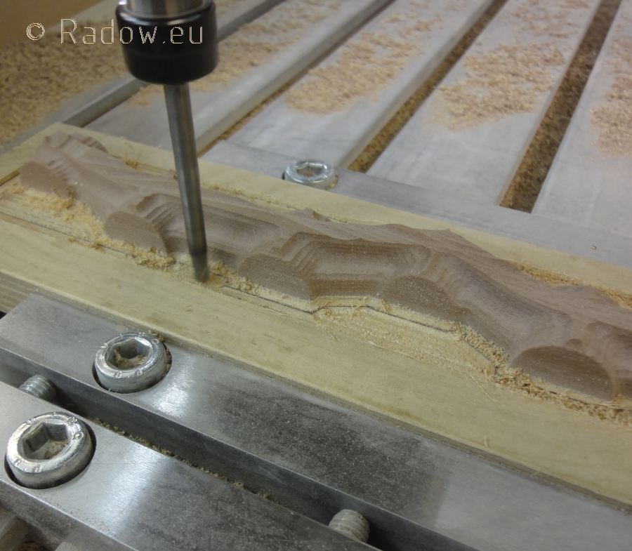
Today I started to build more patterns. This is the suspension bar for (is "of" the better word?) the two slide ways. It is a two-parts mold. This picture shows the rugh machining of the top half.
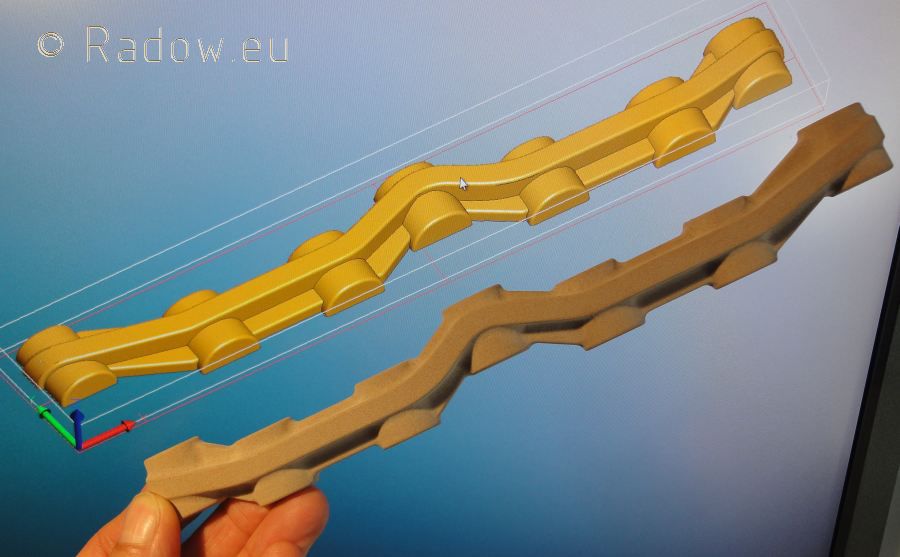
And this is the top part on the screen and the ready machined bottom part in my hand in front of the monitor.
PS:
I really would like to improve my English - so if you find a mistake or some grammar imperfections please send me a private mail with your suggestions at rainer @ radow . org
Slideway suspension bar
Posted: Sun Sep 16, 2012 8:33 pm
by Rainer
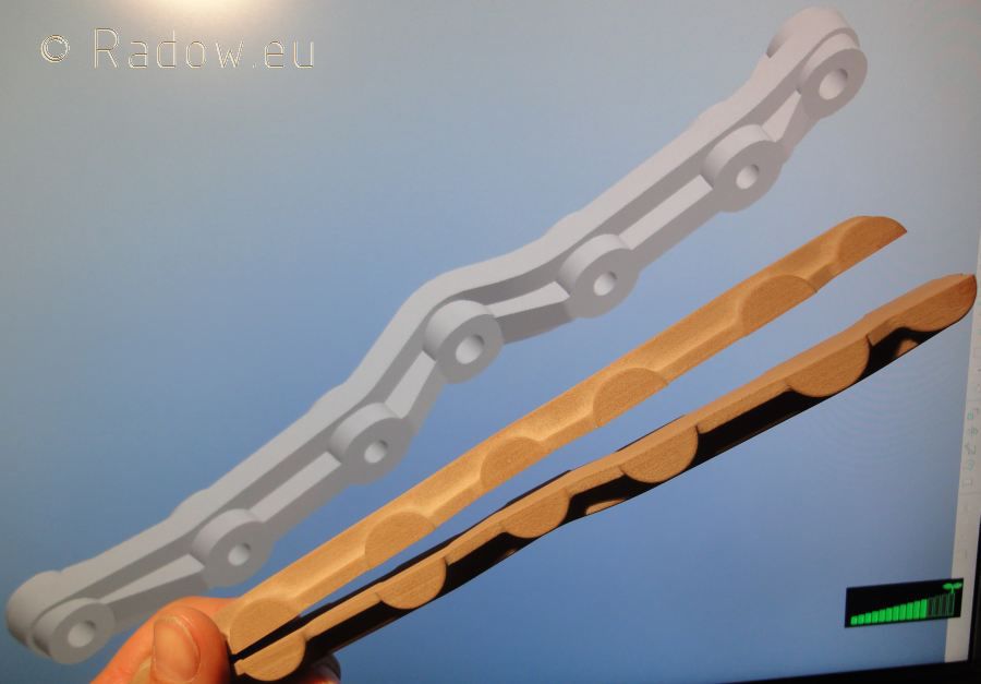
In this minute I finished the second part:
At this animated gif you can find where to place this bar when machined. It's the back view with the piston valve gear rods and it's slideways
Joy Valve Gear
Posted: Sun Sep 16, 2012 8:39 pm
by Rainer
kno3 wrote:... is the valve gear of the Hackworth type? It seems to have a straight slide if I'm not mistaken.
Yes, it has straight slides -
but it is a very simple Joy Type
- with a bad steam distribution
- but only less parts.
Will show some details later.