Page 5 of 22
No Cylinder yet
Posted: Wed Sep 19, 2012 7:53 pm
by Rainer
Hello Boys,
no news from the cylinder in the moment. So I heated up the old oven and poored some aluminum just to test the strength of the slideway suspension bar. Don't know if I want to make it from Aluminum, Bronze or Cast Iron.
I poored it into an open mold - so only half of the bar:

But if you take a close look you can see the tool path in the pattern:
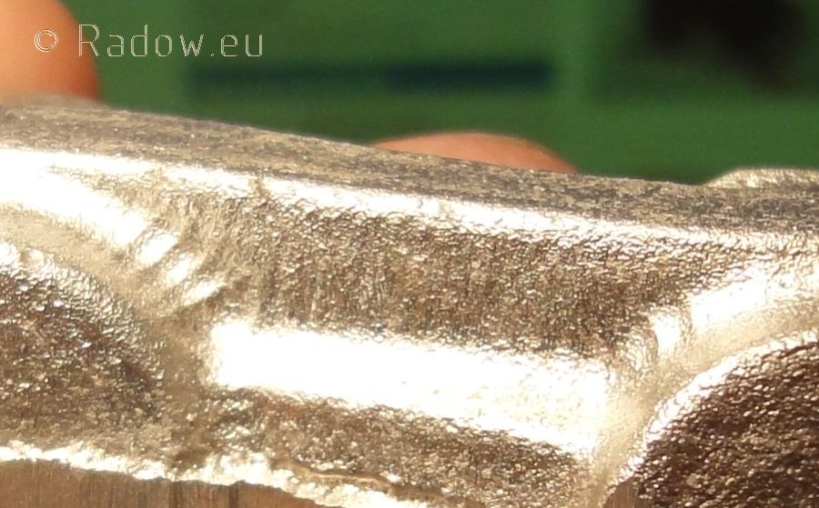
OK - have to use some sandpaper tonight ...
cylinder block - foundry
Posted: Thu Sep 20, 2012 12:48 pm
by Rainer
Foundry told me that they finished the molds for two cylinders in this moment and will pour the cylinder block this friday.
Maybe I can manage to do the 2 hours one way trip by car at monday and show you some pictures here. So please keep your fingers crossed for me!
Re: First core bockes
Posted: Thu Sep 20, 2012 7:02 pm
by artemis
I've crossed my fingers for you. This build is truly exciting - I remember when, several years ago, you talked about building something like this compact German Navy engine. I hope you can make the plans and castings somehow available. Maybe you'll be able to talk to somone during your trip to the US this October. Keep up the flawless work

Thank you
Posted: Fri Sep 21, 2012 7:07 am
by Rainer
artemis wrote:I hope you can make the plans and castings somehow available.
Hope so!
artemis wrote:Keep up the flawless work
Thank you!
Second trial
Posted: Fri Sep 21, 2012 7:13 am
by Rainer
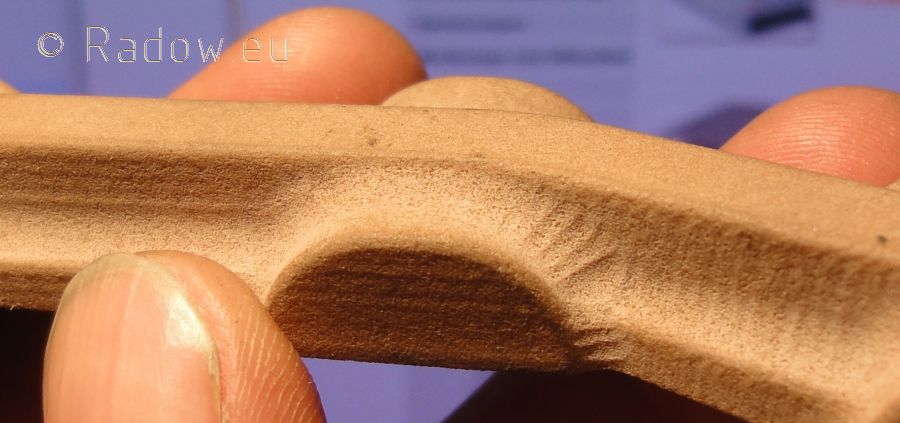
Yesterday I had some time before going home from work. So I have made a second poor of the beam. This time with a two parted sand mold. Bottom part in the sand:
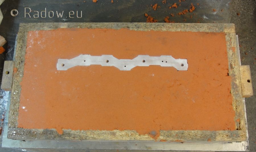
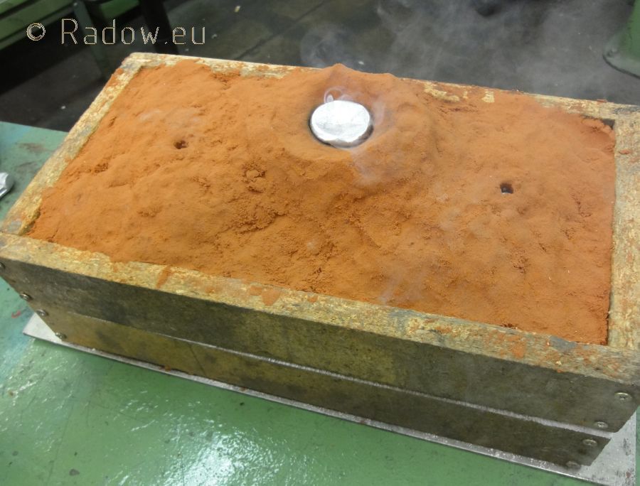
20 minutes later with some aluminum in it. I poured it into the big feeder in the middle till it came out of the air holes left and right.
To separate the good sand from the burned sand I shoveled it out by hand carefully:
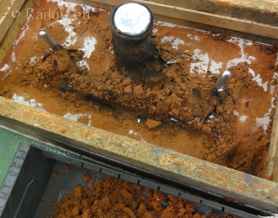
This is an oil-bounded sand. When it becomes hot the oil burns and the sand becomes black.
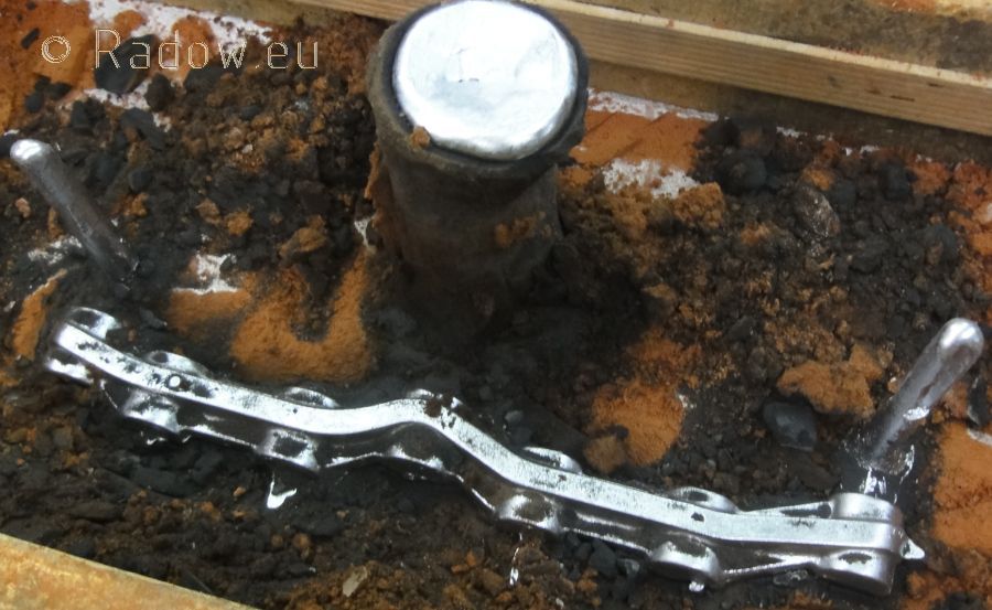
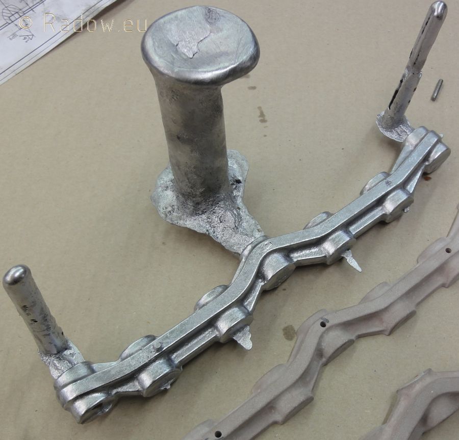
Finished part - just cleaned with water:
Re: First core bockes
Posted: Sat Sep 22, 2012 12:58 am
by Aheadslow
The oil-bounded sand appears to give a very good result. Nice crisp details on that part. I have to agree with Artemis very exciting build and some truly beautiful work . Thanks for sharing this.
oil-bunded sand
Posted: Sat Sep 22, 2012 6:25 am
by Rainer
Aheadslow wrote:The oil-bounded sand appears to give a very good result.
Yes, it's the combination of this sand a the aluminum cast. From my experiences aluminum reproduces fine structures much better than cast iron.
Aheadslow wrote:Thanks for sharing this.
My pleasure!
LP Piston and valve slide
Posted: Sat Sep 22, 2012 7:18 am
by Rainer
Hello again
This weekend I focus on making the pattern for the combined LP piston and valve crosshead guide.
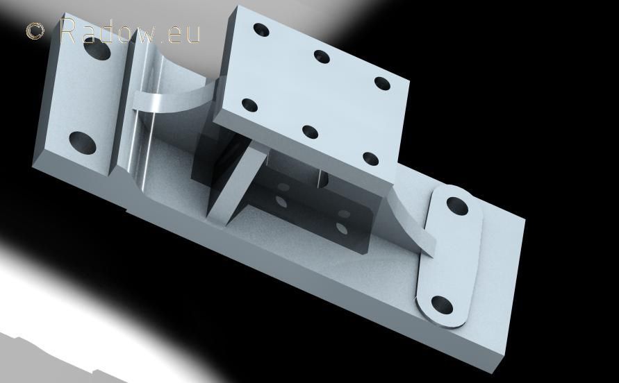
In this view of the sub assembly "d21-nd-gleitbahn-zb" you can get an imagination of its purpose. (Nuts are size M6 and M8)
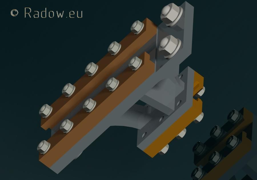
The next photo shows the isolated part "d21-nd-gleitbahn". For the use in the basic CAD model it has no fancy round shapes and lifting bevels. This is to keep the model small and the answering time of the system short. But on todays home computers and such a small model this is not the main reason. Such a simple structure makes it much easier to change basic design issues during all layout phases.
After determining the functions and geometric relations and matching all connecting surfaces, screw holes etc. it is easy to make the pattern from it.
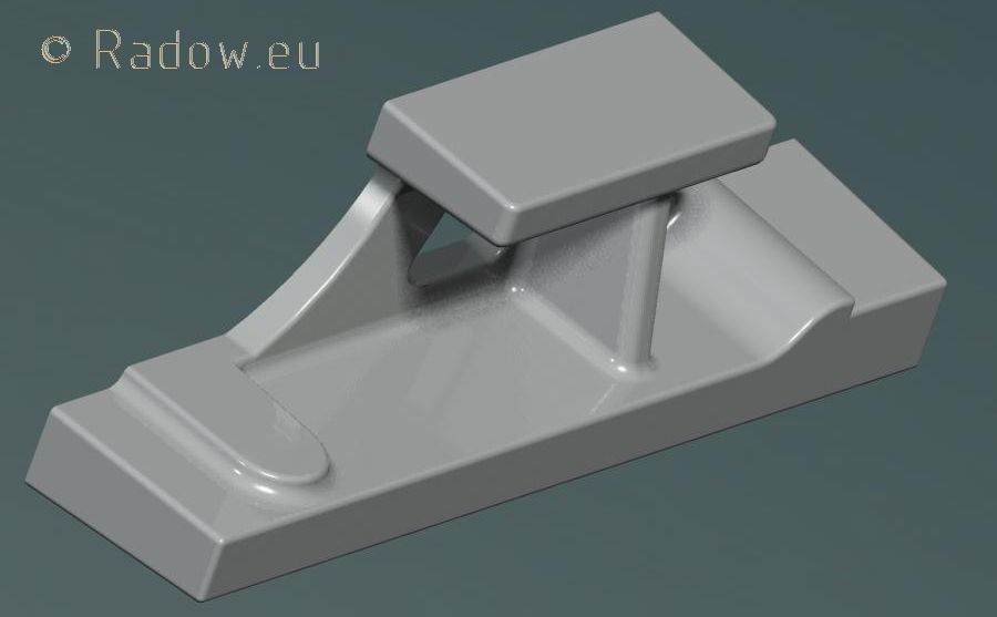
The base of this pattern "d21-modell" is still the part "d21-nd-gleitbahn". First I cut away one half. Then I "glued" on some 3 mm machining allowance where necessary. Next I changed the surface angles to good lifting bevels of 1°, 2°, 3° or even 5° on small edges. Finally I broke the sharp edges with a radius of 1, 2 or 2.5 mm - 2.5 mm because I will use a 5 mm ball nose cutter.
I did it in exactly this sequence because it is the easiest operation to make a half cut of a part but the most "exciting" task to get nice and closed round coutures around the part.
My file "d21-modell" now consists of a link to "d21-nd-gleitbahn" and the description of the operations of cutting, gluing and shaping - but not of the basic geometry.
When someone now decides to change the slide way width for example, I have to do this in the base model "d21-nd-gleitbahn". After that this changes went into the "d21-modell" and automatically changes it - if I am lucky. Sometimes after this operation you have to redesign some lifting bevels etc. because of the change of the basic structure and the impossibility of the derived geometry.
The advantage of this method is that after changes in the concept you mostly have a still stable base design of the steam engine. You only have to correct things in individual files with "standalone" parts.
Saturdays progress
Posted: Sun Sep 23, 2012 1:46 pm
by Rainer
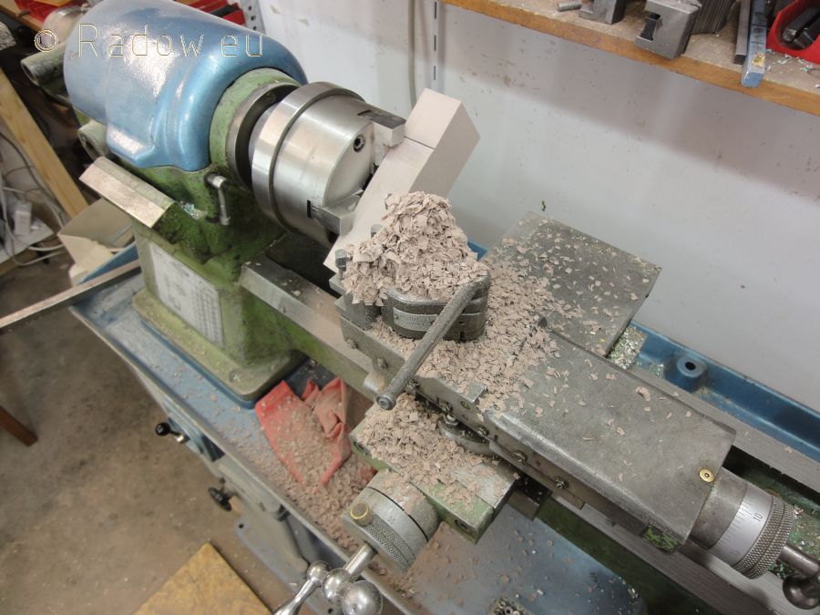
Preparing the raw material - the old-fashioned way
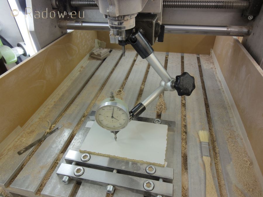
Leveling the milling platform (piece of an old case board)
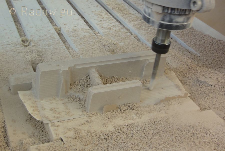
Roughing operation - you can see the double sided tape which holds the workpiece at the milling platform.
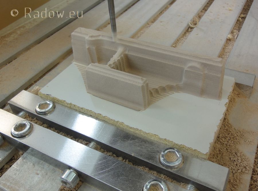
Z-level smoothing
Re: LP Piston and valve slide
Posted: Mon Sep 24, 2012 4:08 am
by artemis
Rainer wrote:Hello again
This weekend I focus on making the pattern for the combined LP piston and valve slide way (better English word please!).
Crosshead Guide