Please don't make crankshafts like this! And don't use Loctite! The torque required of steam launch engine is very high and cannot be compared to model engines. This is a job requiring some design considerations, I did a small contribution to the funnel giving guidelines which I copied onto this forum but it may have been in the old section. At the risk of boring everyone I will repeat it.
Regards Jack
In the pages of funnel there has been numerous items concerning crankshafts and their construction for steamboat engines and probably more tears shed than in any other part of construction. My personal view, is that the methods discussed below are the most suitable and I would not consider any other method bearing in mind that steamboats often operate in conditions of a very high torque to power ratio what is known as a “torque rich” condition, this is often due to the idea that even small boat engines should run at 200 or 300 revs per minute turning a huge propeller, a view I do not necessarily share.
Solid construction, many crankshafts are machined from solid using stock material, If you have a Dean Smith & Grace or another fine large capacity lathe made in Yorkshire, or the midlands all well and good. Carbon steel should be selected of at least 600 N/mm2 tensile strength. I use EN8 generally for this type of work, its easy to machine and is of sufficient strength providing the dimensions are sufficient and (most important) the change in sections are provided with generous radii. The radius at the crankpin and main journals should be at least 0.125 of the journal diameter and the bearings should have a chamfer sufficient to clear this. Ideally the journals should be finished on a crankshaft-grinding machine, automotive repair engineers can usually do this, the grinding process will accommodate the radii and there is no need to leave the crankpin centre bosses on. Modern crankshaft grinders use a wheel head that reciprocates to suit the eccentricity of the crankpin in question.
Should you be a dab hand at pattern making, then S.G. iron could be used although bear in mind the strength of the material will be less than EN8 and the radius is even more important. Many years ago at marine engineering college I saw a film that showed the construction of a crankshaft for a Doxford oil engine (I don’t use the “D” word as the oil engine was invented by Herbert Ackroyd Stuart an Englishman). Anyway the chaps at Doxford & Sunderland had a large forging which was to be made into two crank throws with a main journal between (part of a crankshaft) this was a U shaped forging and one leg of the U was lowered into a pit and the centre part heated up to red heat, the other leg was then twisted though a large angle (forget what) to form a two throw piece. If this can be done with a forging weighting many tonnes I am sure it could be done with a profile cut slab of EN8 to form a two-throw crankshaft. Obviously stress relieving and a large machining allowance are essential, but it could save on material for anyone wishing to try (I have never done this myself).
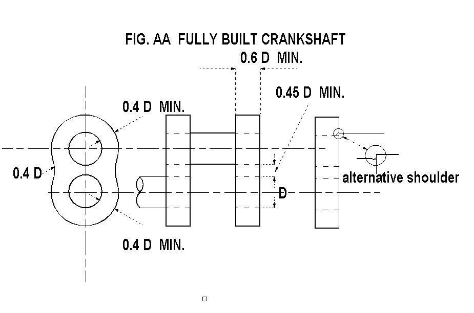
Fully built construction. A fully built crankshaft is one where the main journals and the crankpins are shrunk into holes in each web. The main shaft is kept as a single piece until the shrink process is complete and then cut out before final skimming of the web inner faces if required. This type of construction has the drawback that the fillet radii as mentioned above cannot be used. Many large marine steam engines were built by this method using a web profile similar to fig AA. These were often fitted with pins installed axially along the join between the main shaft and the web. The fitting of any kind of pin is NOT recommended. In the case above the pin could in fact compromise the integrity of the interference fit and pins fitted radially are of limited use as torque transmitters, any pin hole produces a stress point, don’t use them. The same could be said of oil holes, these should only be contemplated with solid crankshafts and if used all drilled ends should be carefully radiused. The surface finish of shrink fits should be as good as possible, grinding is best but careful turning and polishing will suffice, the idea that a “rough” surface will grip better is nonsense and purposely roughed surfaces should be avoided.
The correct interference fit is 1/600 of the diameter concerned.
i.e. 1.67 thou per inch of diameter, obviously a tolerance needs to be used but it should be a close to this as possible. The selection of material is very important and 600 N/mm2 tensile strength is again the minimum particularly for the webs. The minimum web thicknesses both axial and radial and the ligament width between pins shown on the drawings must be adhered too to avoid over stressing the webs, which would lead to failure of the shrink fit.
I personally would not use the fully built method unless I was constructing a very large shaft, as I believe the “semi built” method is superior,
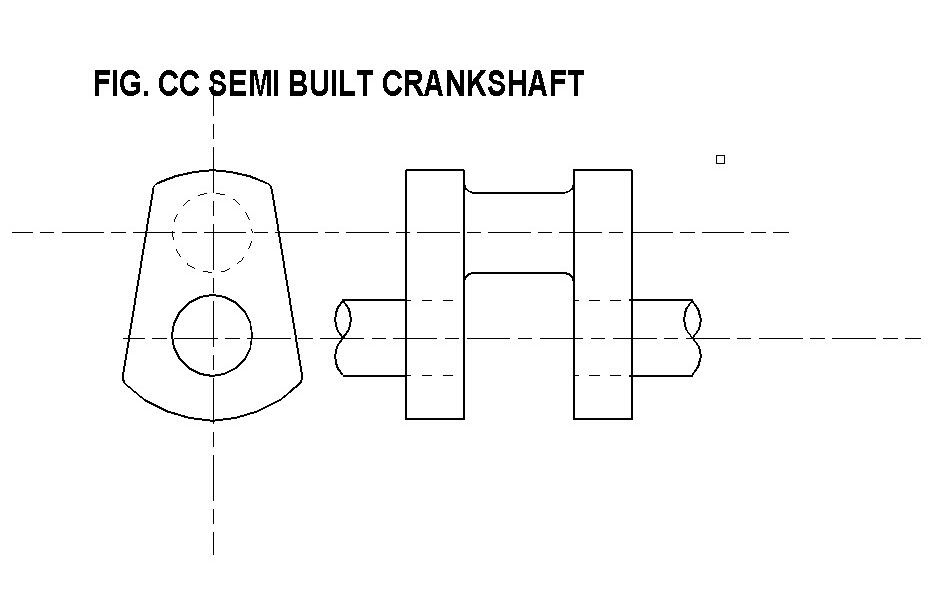
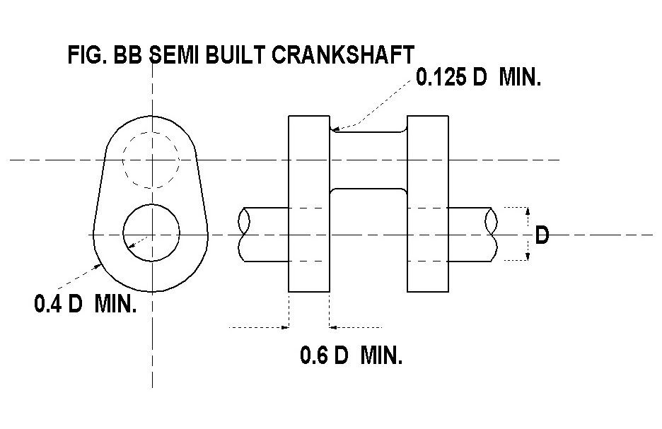
Semi-built construction. This is the method used for large marine crankshafts weighing 300 tonne or more and transmitting over 100000 H.P. the main reason for this method is two fold.
A) A large radius can be accommodated on the crankpin/web corner. And B) The vertical distance between the diameter of the crankpin and the main journal can be made small (which is not possible with two adjacent shrink fits) and therefore the journal diameters can be made larger for a given stroke of engine.
Each cylinder unit consists of a pair of crank webs and the crankpin machined from solid, these are then shrunk onto the main shaft as in fully built construction. If the profiles shown in fig BB or CC are used the web units can be machined from round stock with a minimum of waste and machining time. As with solid construction it’s often easiest to chop out the bulk of the crankpin area using a milling machine and dividing head rather than the lathe.
Fully built using vacuum brazing. I am building two engines currently which came with partly finished crankshafts, this has apparently been vacuum brazed, I am not familiar with this construction method but believe it is a “high tech” process used a lot in industry. The integrity of the brazed joints is probably good but the design problems of the lack of radii are still a concern especially as this is a three-throw crank running in six main bearings, the cranks are radially pinned but this is probably for assembly reasons. The photo shows the second crankshaft as received from the brazing process, I intend to reduce the size of the hideous balance weights and fillet out the right angle internal corner on the webs, a very poor idea both mechanically and aesthetically, had I built these myself I would not have fitted balance weights at all on a three throw crankshaft.
Should you consider the use of balance weights I would suggest the web construction as in fig DD this is a fairly traditional design for launch engines, additional weights can be attached on the insides provided the tapped holes are well away from the shrink fit or they can be part of the web if fully built, either way its obvious that the weights should clear the connecting rod. Personally I believe that weights even on a two crank ninety-degree shaft are rather a waste of effort as you can never fully balance such an engine without recourse too much complication, but that’s another subject.