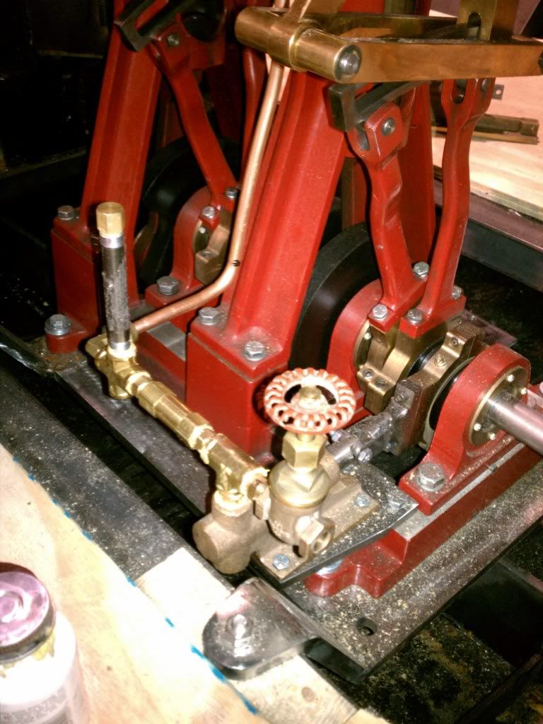
Piping up the pumps. Check these pics and see if everything looks alright. One question I have is about the inline checkvalve, can it be located and work properly where it is?
The Crane gate valve is for the pump bypass, not that I'll need it with this pump. There will be a manual pump on the engineers side of the engine that will connect to the cross on the other side. Not shown in the pic, down in the engine well to the right is a 1/2" Perko sea strainer.
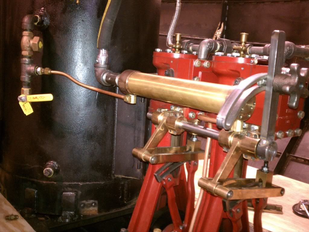
Here is the routing at the heat exchanger/exhaust manifold:
The ballvalve on the feedwater input at the boiler, will connect to a 12volt pump mounted under the floor. Open to fill, close it to fire.
Other than lag the pipes once you've tested the performanance and functionality,
That gate valve may be a bit course for the job.....maybe. You may want to find a small globe or large needle valve...but try it out and see....hell it's plumbed!
Counter flow would be a bit more efficient, but its a double simple, and the steam is coming from two places, so it probably doesn't matter.
Your pressure dome and plumbing shoule be bigger I think....same bore as the pump....to prevent hammering....but then that will depend on your speed...so run her! It's plumbed!
ASME Boiler Code always requires a check valve , followed by an isolation valve, just upstream of the boiler feed point. It looks as if you have no isolation valve between the feed heater and the boiler. Normally the check valve should be upstream of the isolation valve, but the Code allows the check valve mounted downstream of the isolation valve for single boiler installations, which is the case here.
The check valve should be mounted horizontal, although a check valve with a swinging disc will usually work OK if mounted in a vertical run of pipe. At our company, mounting of swing check valves in vertical piping runs is not allowed. If this is a "Lift check", then it definately should be mounted in the horizontal run of pipe.
The first instinct was to have a globe valve at the feedwater input at the boiler. Was warned against it, as folks forget to open them and destroy the feedpump.
It is a "Spring lift check valve" Rated for high pressure steam. I think I will go ahead and move it to the horizontal though. If the spring were to fail..
Question I've been pondering: In Propane where large quantities are stored, at every boss on the vessel, there is fitted an excess flow check. It is essentially a spring loaded disk that will snap shut if there is failure of a pipe or valve, They are rated in GPM by application. Why aren't these used in steam boilers? Seems if they were used on all boiler connections except the relief valve, would be much safer.
If the spring should fail the steam pressure from the boiler should keep it shut.I have an isolation valve between the check valve and boiler.Should something happen down the line I can close down the boiler.And yes funny things happen when that valve is closed at start-up! I have the handle hanging nearby so I don't have it turned off unless necessary! I've seen a pressure relief valve installed downsteam[towards the pump] from the check valve.This would be set above boiler pressure of course and would eliminate damage to the pump if the isolation valve were mistakingly closed.Den
I have to agree with Dave concerning the feedwater bypass valve. I too would use a globe or needle valve there. It makes for much finer tuning and finding that "sweet spot".
"I've seen a pressure relief valve installed downsteam[towards the pump] from the check valve."
The rules say you have to have relief valves on any piping or pressure vessel that could be overpressured , either by a pump or, in the case of boilers, a fire or heat source. This requires a relief valve on a positive displacement pump that is engine driven.
You can also have a relief valve required for the manual (hand powered) pump, if it has the capability of overpressurizing the piping or feedwater heater, and can be isolated from the relief valve that protects the machinery from overpressure from the engine driven pump. It is generally a good idea to have isolation valves for each pump, so that if the pump valves hang up, you can isolate the bad pump and continue with the other pump.
My manual feed pump is configured such that I can put all my weight on the pump handle and not overpressurize the piping, so for this pump there is no relief valve. The engine driven pump could go past 1000 psi if the discharge is isolated, and the engine is running, so that piping has to have a relief valve.
With respect to naming conventions, in the USA the word "downstream" means "in the direction of flow", and "upstream" means in the direction opposite the normal flow. So the pump, and its relief valve, is "upstream" of the boiler check valve. Am I missing something here?
Let's eliminate "upsteam and downstream" with "boiler side of check valve and pump side of check valve"!! I never read instructions so I would never make a mistake! I thought I did once but I was wrong! While you're at it Ron why not throw in a pressure gauge [and another isolation valve]This way you could see what kind of pressure your pump is putting out,establish a normal operating pressure,and be able to recognize when something is going wrong with your pump.I haven't got this yet but it is on my want list.It's getting complicated isn't it? Your photo was so simple and would work but it's now so complex no one can steal the boat when it's tied up at your local marine pub!! Den
Fred's right...saw the ball valve and had a brain cramp...you need isolation between the check and the boiler.
...and a relief valve. I put on on my engine driven pump and the first time out I had a piece of crud get in the seat after I forgot to open the isolation valve. It wouldn't reseat, so I took it out and plugged it....unfortunately, I have'nt put it back in since..... ....but I will.