Hello Boys,
a friend of mine had some trouble with his sand cores. He has send me his ingredients and I have made some cross tests.
Have a look at youtube:
http://www.youtube.com/watch?v=EVVCS-jY ... e=youtu.be
First core box
-
johngriffiths
- Warming the Engine

- Posts: 86
- Joined: Fri Nov 20, 2009 7:13 pm
- Boat Name: Tenacity
Re: First core bockes
Interesting set of tests Rainer.
A point to consider is which core is going to vent the best. The core has to last one cast only so a balance has to be struck between the ability to collapse slightly as the metal solidifies, to be pervious to gasses and to resist the eroding effects of the liquid metal as it flows past as well as retaining its form.
All the best
John
-
Rainer

- Full Steam Ahead

- Posts: 306
- Joined: Sun Nov 22, 2009 5:42 pm
- Boat Name: Emma and Molly
- Location: Hannover, Germany
- Contact:
Sand core making
That's true but air has "little heads" so the sand should have no "dust" in it and you also should use only the minimum percentage of water glass not clogging the little air canals. If the CO2 will find it's way to harden the sand, the gas produced whyle pouring will come out the same way.johngriffiths wrote:A point to consider is which core is going to vent the best.
My 0.1 to 0.4 mm grain will give very good reproductions of fine details and also vent enough. You have to make some vent holes into massive cores of course.
A good water glass will support this by loosing it's strength after a certain time in hot conditions. Ideally exact at that time when the metall starts to solidify - but that is not a question of streght in cold conditions!johngriffiths wrote:... the ability to collapse slightly as the metal solidifies ...
Especially for small parted and highly detailed little steam engines I like my sand - water glass combination best.
Rainer
www.steamboating.de
www.steamboating.de
-
Rainer
- Full Steam Ahead
- Posts: 306
- Joined: Sun Nov 22, 2009 5:42 pm
- Boat Name: Emma and Molly
- Location: Hannover, Germany
- Contact:
valve cylinder bore - first trial
Hello steamboaters,
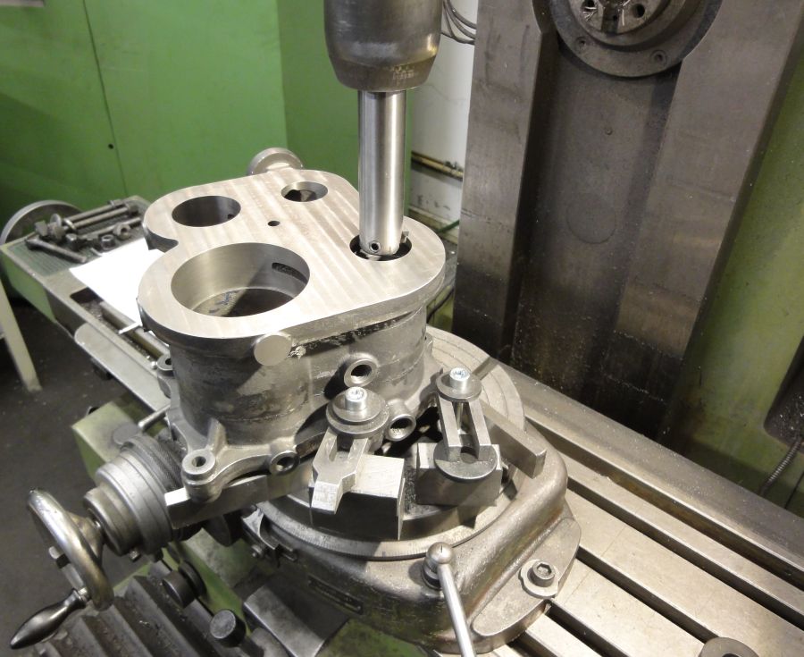
today I have made the first trial of boring the piston valve cylinder on the conventional mill. The challenge is to align the bore to the already machined stuffing box at the bottom of the cylinder. Because the bottom cover is integrated in the cylinder block, you have no chance to go through the cylinder with the boring bar.
So I have machined a device with a close fit to the stuffing box and two screws to secure it on top of the mill table. With a gauge in the milling shaft I could align the table perfectly to the boring center.
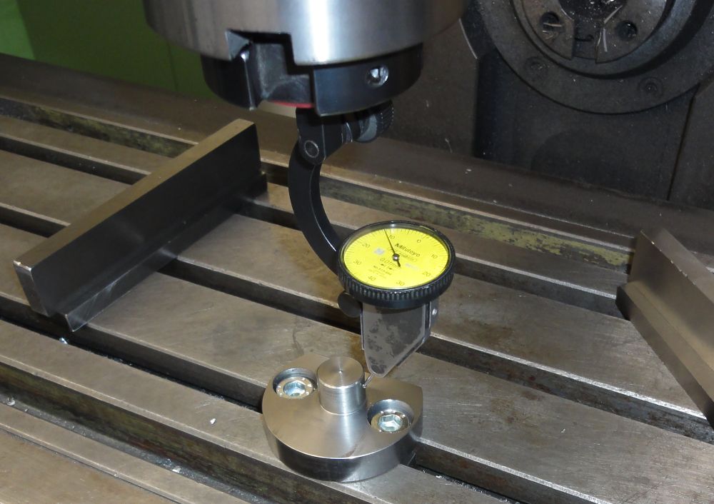
After that was done I aligned the cylinder block via this device to the stuffing box of the LP-valve-rod.
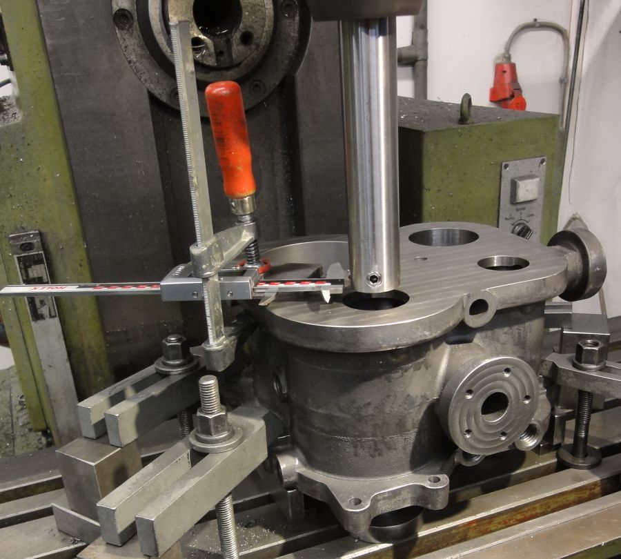
The boring bar is also self made. It is made from a diameter 32 mm round steel. At the end it has a diameter 12 hole to hold ordinary boring tools for the lathe. This will be secured by a M10 grub screw. With an ordinary digital caliper hold by a bar clamp I am able to set up the single-point tool to the correct diameter - after some trials
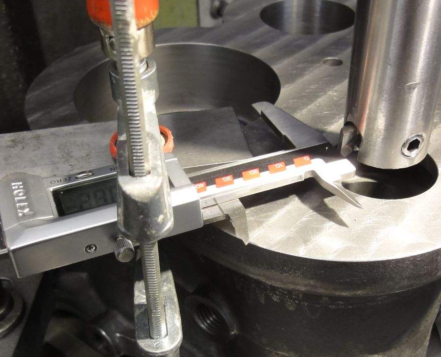
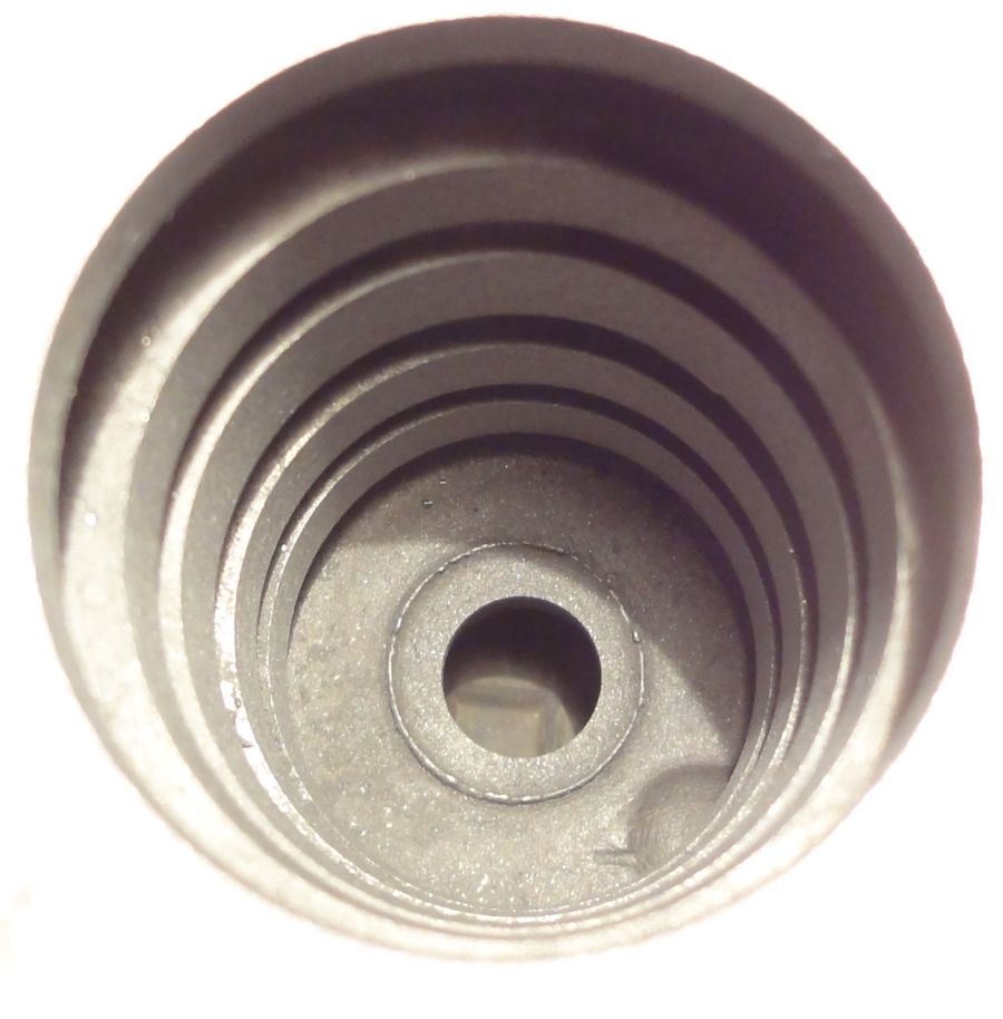
I am happy with the first results. This bore is 43 mm in diameter and 120 mm deep. I have to widen it to 45 mm. The ports are unmachined as they came out by casting -will machine this after the bore is done.
today I have made the first trial of boring the piston valve cylinder on the conventional mill. The challenge is to align the bore to the already machined stuffing box at the bottom of the cylinder. Because the bottom cover is integrated in the cylinder block, you have no chance to go through the cylinder with the boring bar.
So I have machined a device with a close fit to the stuffing box and two screws to secure it on top of the mill table. With a gauge in the milling shaft I could align the table perfectly to the boring center.
After that was done I aligned the cylinder block via this device to the stuffing box of the LP-valve-rod.
The boring bar is also self made. It is made from a diameter 32 mm round steel. At the end it has a diameter 12 hole to hold ordinary boring tools for the lathe. This will be secured by a M10 grub screw. With an ordinary digital caliper hold by a bar clamp I am able to set up the single-point tool to the correct diameter - after some trials
I am happy with the first results. This bore is 43 mm in diameter and 120 mm deep. I have to widen it to 45 mm. The ports are unmachined as they came out by casting -will machine this after the bore is done.
Rainer
www.steamboating.de
www.steamboating.de
-
DetroiTug

- Full Steam Ahead
- Posts: 1863
- Joined: Fri Nov 27, 2009 5:56 pm
- Boat Name: Iron Chief
- Location: Northwest Detroit
Re: First core bockes
A little trick for setting a boring bar like that. Clamp a tall parallel in line with the X or Y axis. Then pick up the edge of the parallel with the edge finder. Then put the boring bar back in and move off the parallel the distance equal to the radius of the bore, then set the cutter to the vertical face of the parallel. Sweep it with paper in between etc.
I am not sure which control you are using, but when setting the spindle to the parallel make it an offset i.e. G55, G56 etc. Then you can just call up the offset when the boring bar needs to be adjusted or checked.
-Ron
I am not sure which control you are using, but when setting the spindle to the parallel make it an offset i.e. G55, G56 etc. Then you can just call up the offset when the boring bar needs to be adjusted or checked.
-Ron
-
Rainer
- Full Steam Ahead
- Posts: 306
- Joined: Sun Nov 22, 2009 5:42 pm
- Boat Name: Emma and Molly
- Location: Hannover, Germany
- Contact:
Re: First core bockes
Hello Ron,
thanks for your thoughts! Will safe your method for next possible job. You never can have enough recipes for machining
In this case it is quite easy because the dial gauge is mounted in the spindle and can be turned in the spindle around the center jig mounted on the table. Than you only have to move x and y till the dial gauge don't move any longer. After that you found the "perfect center".
Rainer
www.steamboating.de
www.steamboating.de
-
Rainer
- Full Steam Ahead
- Posts: 306
- Joined: Sun Nov 22, 2009 5:42 pm
- Boat Name: Emma and Molly
- Location: Hannover, Germany
- Contact:
Control edge
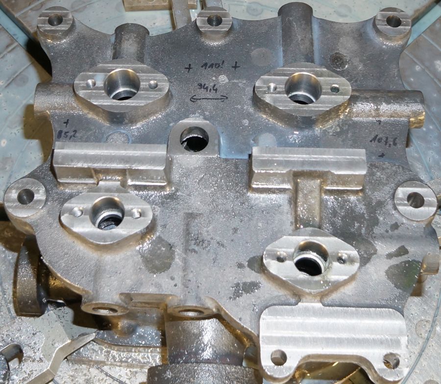
Today I machined the control edges of the LP piston valve cylinder. In this view you can identify the situation:
HP piston valve cylinder at the left - LP piston valve cylinder at the right
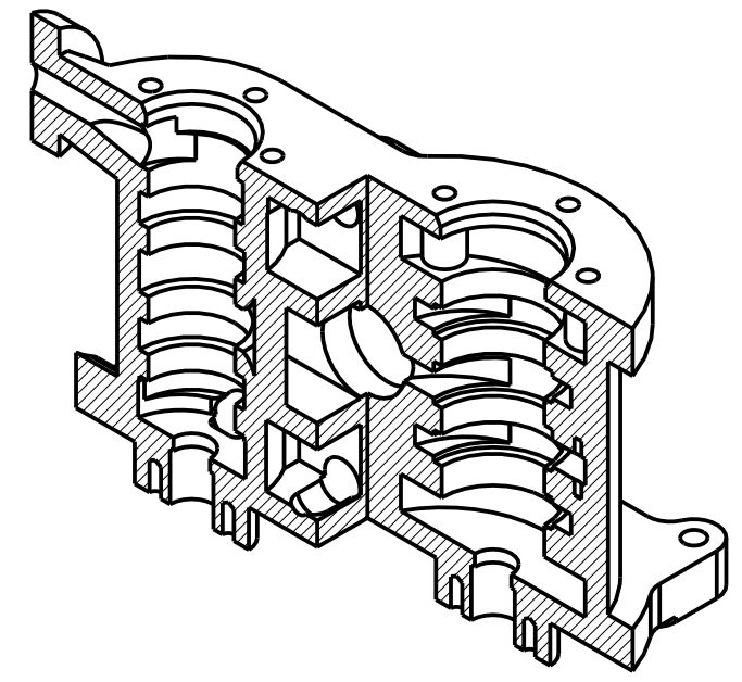
The steam ports are already build by the sand cores. This cores are forming the control edges with about 2 mm machining allowance. So now I had to remove this machining allowance to get sharp and well positioned control edges for the piston valve. In the drawing above you can identify the machined surfaces as rings with little steps up/down to the casted surfaces.
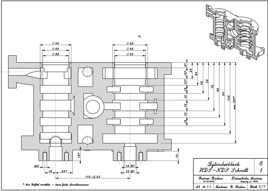
At the following drawing you will find all the control edges and the dimensions of the cylinders (all dimensions in mm - right click to all my pictures to open them enlarged).
Because I am back at the fully manual operated mill, I used a circular table and my self made boring bar. The cylinder bore was aligned to the circular table center. After bringing the boring bar to the appropriate depth I moved the x-axis in steps of 1 mm. After each step I turned the circular table 360 degrees by hand. This produced the necessary groves/control edges.
To cut the upper and the lower control edge I had to mount the cutting tool up- and downward while turning the spindle clockwise or counterclockwise (upward position shown)
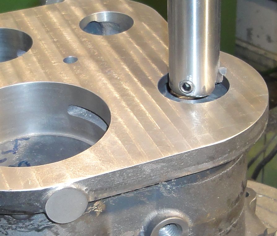
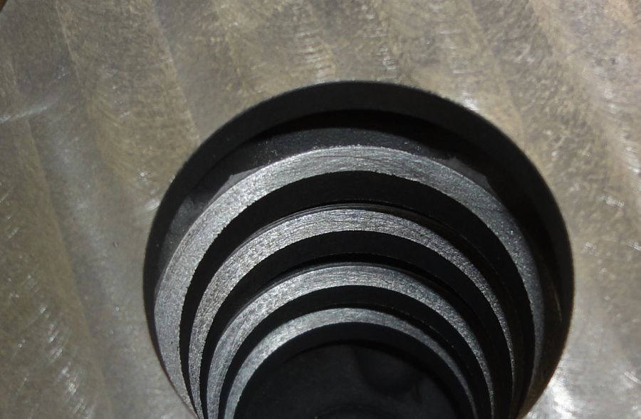
The result is fine. It is not necessary to have a super fine surface at the steps but to have a sharp edge to the cylinder surface. No defects in the casted part. But hard to take a picture of a hole dia 45 and 120 deep ...
HP piston valve cylinder at the left - LP piston valve cylinder at the right
The steam ports are already build by the sand cores. This cores are forming the control edges with about 2 mm machining allowance. So now I had to remove this machining allowance to get sharp and well positioned control edges for the piston valve. In the drawing above you can identify the machined surfaces as rings with little steps up/down to the casted surfaces.
At the following drawing you will find all the control edges and the dimensions of the cylinders (all dimensions in mm - right click to all my pictures to open them enlarged).
Because I am back at the fully manual operated mill, I used a circular table and my self made boring bar. The cylinder bore was aligned to the circular table center. After bringing the boring bar to the appropriate depth I moved the x-axis in steps of 1 mm. After each step I turned the circular table 360 degrees by hand. This produced the necessary groves/control edges.
To cut the upper and the lower control edge I had to mount the cutting tool up- and downward while turning the spindle clockwise or counterclockwise (upward position shown)
The result is fine. It is not necessary to have a super fine surface at the steps but to have a sharp edge to the cylinder surface. No defects in the casted part. But hard to take a picture of a hole dia 45 and 120 deep ...
Rainer
www.steamboating.de
www.steamboating.de
-
fredrosse

- Full Steam Ahead
- Posts: 1930
- Joined: Fri Nov 20, 2009 5:34 am
- Boat Name: Margaret S.
- Location: Phila PA USA
- Contact:
Re: First core bockes
Is it correct that the piston valves will have no liner sleeves? I thought that sleeves are necessary to avoid having the piston valves (or piston valve rings) catch upon the ports, and I have seen many cylinder liners with circular (or nearly rectangular) ports to provide guidance for the piston valve. I also thought the original drawings show a piston valve sleeve, but the resolution is poor, as is my eyesight.
It would seem to me that a very close fitting piston valve would need additional guidance to avoid this problem, or the piston valve to port clearances would have to be somewhat large, and thus leak steam.
Judging from your history of considering everything technical, it seems that you probably have already thought about these issues.
-
Rainer
- Full Steam Ahead
- Posts: 306
- Joined: Sun Nov 22, 2009 5:42 pm
- Boat Name: Emma and Molly
- Location: Hannover, Germany
- Contact:
liner
Yes, that is true and corresponds to the original design. Only with this feature you can machine the port edges (is there a better steam talk word?) direct into the casted part.fredrosse wrote:Is it correct that the piston valves will have no liner sleeves?
At my Arkona engine I am using the classic design with a liner and port bridges for piston guidance:
From left to right: casted valve chest, liner, piston valve.
Liner - intermediate machining status - top and bottom not trimmed - pors at the right already filed to a squared shape.
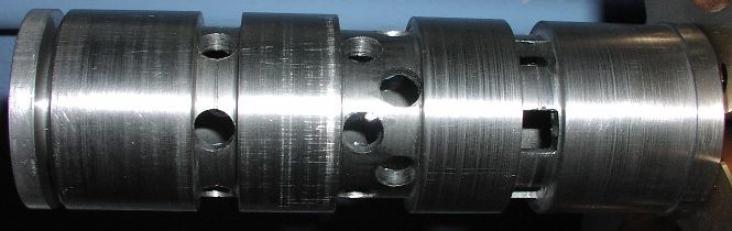
But even here I do not use piston rings. Maybe I could save some coal with valve piston rings but I prefer the "kiss" principle and have no performance problems since 2005...
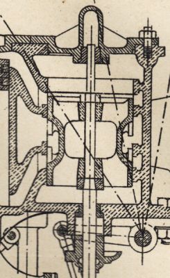
It was not me. the engineers from 1902 did this already. At this blow-up you can identify the solution. If this is a good or bad idea will be shown in some month (years...) - at least I can bore a bigger hole and use the regular liner sleeve solution afterwards.fredrosse wrote:I thought that sleeves are necessary to avoid having the piston valves (or piston valve rings) catch upon the ports ... it seems that you probably have already thought about these issues.
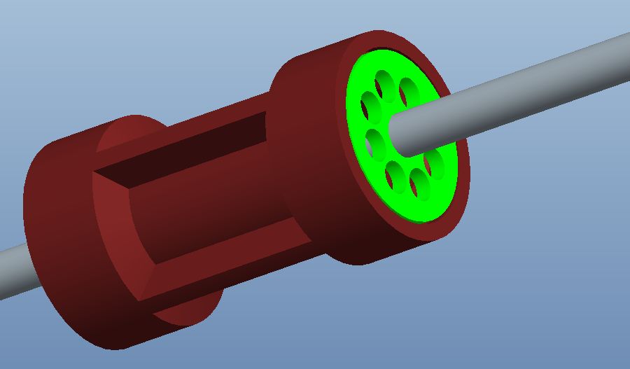
This is my rough design of the piston valve with the integrated "bridges" to protect the piston from "falling" into the ports.
Rainer
www.steamboating.de
www.steamboating.de